Table of Contents
Advertisement
Quick Links
Download this manual
See also:
Quick Manual
Advertisement
Table of Contents

Related Manuals for Crestron n TPMC-12


Summary of Contents for Crestron n TPMC-12
- Page 1 Crestron TPMC-12 ® Isys 12” Tilt Touch Screen Operations Guide...
- Page 2 RealNetworks, Inc. in the United States and/or other countries. Other trademarks and trade names may be used in this document to refer to either the entities claiming the marks and names or their products. Crestron disclaims any proprietary interest in the marks and names of others.
-
Page 3: Table Of Contents
Tilt Angle Tension Adjustment ................. 43 Recommended Cleaning.................... 43 Programming Software ......................44 Earliest Version Software Requirements for the PC ..........44 Programming with Crestron SystemBuilder.............. 44 Programming with SIMPL Windows ................ 44 Programming with VisionTools ................47 Embedded Applications..................... 51 Defaults for Embedded Windows Applications ............ -
Page 5: Isys 12" Tilt Touch Screen: Tpmc-12
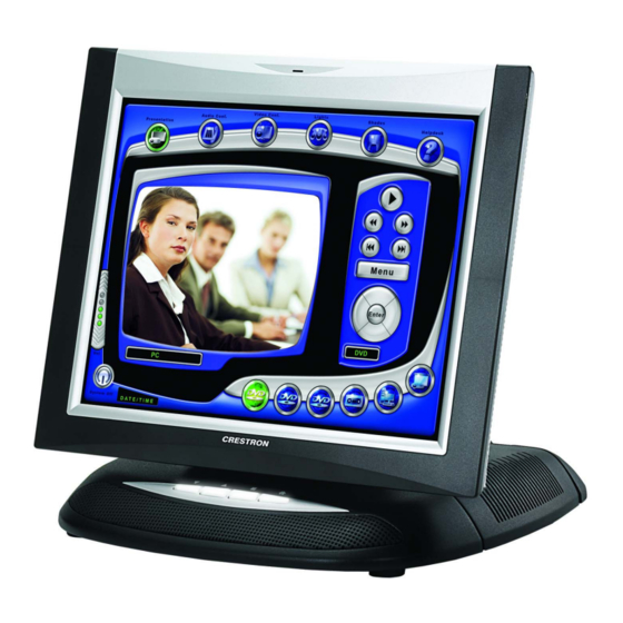
• WAV file audio feedback • Built-in amplified speaker system and microphone ® ® • QuickMedia * and Crestron Home CAT5 connectivity • ® High speed Ethernet and Cresnet communications • Rear panel USB ports and memory card slot •... - Page 6 Crestron TPMC-12 Touch Screen Control Crestron touch screens offer an ideal user interface for multimedia presentation, home automation and much more, providing a wide open canvas for the creation of custom control screens tailored to the needs of the end user. Touch screens do away...
- Page 7 CAT5 AV Connecting external audio and video sources to the TPMC-12 is facilitated using inexpensive CAT5 wire, enabling direct connection to Crestron’s popular CAT5 balanced audio and video distribution switchers. A single video input port accepts signals from composite, S-video and standard definition component sources over wiring distances of up to 750 feet (229 meters).
-
Page 8: Specifications
® Crestron IP Intercom, NetMeeting , Remote Desktop, VNC Viewer , Java™ Runtime, Crestron MediaMarker™ Notebook, Crestron Keyboard, Adobe Acrobat Reader, WordPad, MS Word Viewer 2007, Excel Viewer 2007, PowerPoint Viewer 2007. Ethernet 10BASE-T/100BASE-TX/1000BASE-T, auto-switching, auto-negotiating, auto-discovery, full/half duplex, TCP/IP,... - Page 9 Single window scalable to full screen, input Features switching between QM and VIDEO inputs, gamma correction, line doubling Streaming/File Formats MPEG4 and MJPEG via Crestron MJPEG Viewer, plus all formats supported by the embedded media player applications Audio Hardware Features...
- Page 10 4. Refer to “Identity Code” on page 15 for details. 5. The latest software versions can be obtained from the Crestron Web site. Refer to the NOTE following these footnotes. 6. Crestron 2-Series control systems include the AV2 and PRO2. Consult the latest Crestron Product Catalog for a complete list of 2-Series control systems.
-
Page 11: Physical Description
® Crestron TPMC-12 Isys 12” Tilt Touch Screen Physical Description This section provides information on the connections, controls and indicators available on your TPMC-12. TPMC-12 Physical View ® 12” Tilt Touch Screen: TPMC-12 • 7 Operations Guide – DOC. 6675C... - Page 12 ® Isys 12” Tilt Touch Screen Crestron TPMC-12 TPMC-12 Overall Dimensions (Front View) 12.85 in (327 mm) 10.43 in (265 mm) 12.15 in (309 mm) 11.60 in (294 mm) ® 8 • Isys 12” Tilt Touch Screen: TPMC-12 Operations Guide – DOC. 6675C...
- Page 13 ® Crestron TPMC-12 Isys 12” Tilt Touch Screen TPMC-12 Overall Dimensions (Side View) 10.71 in (272 mm) 12.40 in (315 mm) TPMC-12 Connectors ® 12” Tilt Touch Screen: TPMC-12 • 9 Operations Guide – DOC. 6675C Isys...
- Page 14 ® Isys 12” Tilt Touch Screen Crestron TPMC-12 Connectors, Controls & Indicators CONNECTORS DESCRIPTION CONTROLS & INDICATORS BUTTONS (4) Backlit “hard key” buttons, programmable (1) Miniature recessed hard reset button, reboots the touch screen (1) 4-pin 3.5 mm detachable terminal block...
- Page 15 1. An interface connector for the NET port is provided with the unit. 2. Refer to “Push Button Programming” on page 50 for details. 3. Contact Crestron for a current list of compatible devices and embedded applications. To ensure reliable performance, new device drivers and applications are available only from Crestron through firmware updates.
- Page 16 ® Isys 12” Tilt Touch Screen Crestron TPMC-12 5. The eight-pin RJ-45 QuickMedia transport port accepts CAT5E/CAT6 carrying audio, video and microphone signals. The QM input port conforms to the 568B wiring standard. Refer to the following table for connector pinouts.
-
Page 17: Setup
100BASE-T standard. Crestron takes advantage of this specification for a variety of audio and video applications. When using a Crestron wiring solution, the CresCAT-IM (or D) wire can carry audio and video signals up to 500 feet (152 meters) (observe distance limitations based upon power consumption for the device in use). - Page 18 This phenomenon is due to the added resistance and capacitance of longer cable lengths and is not peculiar to either Crestron and/or QuickMedia systems. To ensure sufficient bandwidth, the maximum aggregate cable length should not exceed 450 feet. The use of lower- resolution signals may allow increased cable length but must be tested by the installer with the sources to be used.
-
Page 19: Identity Code
The IP ID is set within the TPMC-12’s table using Crestron Toolbox. For information on setting an IP table, refer to the Crestron Toolbox help file. The IP IDs of multiple TPMC-12 devices in the same system must be unique. - Page 20 “Security” window. Refer to “Security” which starts on page 18 for more information. 4. When the “Crestron Debug Output” window appears (shown in the following diagram), select Project | Enter Setup Mode to enter the setup menu (refer to “Setup Menu Details” on page 18).
- Page 21 ® Crestron TPMC-12 Isys 12” Tilt Touch Screen “Setup/Calibrate” Window 3. Select Enter Setup Mode. The setup menu will be displayed as shown in the illustration below. NOTE: Select Exit Setup Mode to exit the setup menu. TPMC-12 Setup Menu NOTE: Another way to enter the setup menu (after a project has been loaded) is to touch the screen during boot up when you see the “Preparing to Load Project”...
- Page 22 (i.e. you will not be able to bring up any setup window via a digital join). For more information about Annotation mode, refer to ® ® “About Annotation Mode” in the Crestron VisionTools (VT Pro-e ) Help file. Security The Security button opens the “Security Setup”...
- Page 23 ® Crestron TPMC-12 Isys 12” Tilt Touch Screen and provides a location to save files. To further customize the installation, network drives containing compiled touch screen project files can also be mapped. “Network Connections” Window To add a new network connection, touch Add….
- Page 24 ® Isys 12” Tilt Touch Screen Crestron TPMC-12 “Setup Proxy” Window To setup a proxy server, select Use Proxy Server. 1. Enter the IP address or name of the proxy server. 2. If desired, specify addresses that should not use the proxy server (i.e.
-
Page 25: Touch Screen
NOTE: The touch screen’s calibration routine can also be accessed through Crestron Toolbox if the touch screen is connected to a control system via Cresnet and/or TCP/IP by selecting the device from the Network Device Tree and right-clicking the ®... - Page 26 ® Isys 12” Tilt Touch Screen Crestron TPMC-12 device to select Functions | Setup Mode…. Select Enter Calibration Mode to begin calibration. When Touch Screen Test is touched, the test screen will be displayed (refer to illustration below). This screen allows the user to test the touch screen response at 17 points on the screen.
- Page 27 ® Crestron TPMC-12 Isys 12” Tilt Touch Screen Display Output Touching Display Output shows the display resolution of the touch screen and provides test charts for adjusting skew, peak and boost settings on a remote display. “Display Output” Window Select the following Test Patterns, in the following order and adjust the display as necessary.
- Page 28 NOTE: When selecting Browse, the contents of the “Recent” folder will not be available. NOTE: Projects can also be loaded via Crestron Toolbox. NOTE: If External is checked, the display list cannot be viewed via Crestron Toolbox. NOTE: When loading a project to an external storage device (e.g. MMC card or flash drive), a subdirectory (not the root) must be used as the working path.
- Page 29 ® Crestron TPMC-12 Isys 12” Tilt Touch Screen Current Loaded Firmware displays the version of the current firmware. In the Load New Firmware section, touch Browse and select the firmware file (i.e. the .csz or .zip file) to be loaded from a network drive, USB device or flash drive.
- Page 30 For more information on peak and boost settings, refer to the latest revision of the Crestron MediaManager Applications Guide (Doc. 6244). NOTE: The Input (CH) tab of the “Video Setup” window does not have adjustments for Peak, Boost and Preset.
- Page 31 ® Crestron TPMC-12 Isys 12” Tilt Touch Screen Manage Presets Use the Manage Presets tab to copy presets for position, size and color for one source to other sources. “Video Setup” Window – Manage Presets Tab Audio Touch Audio to open the “Audio Setup” window. The General tab of the “Audio Setup”...
- Page 32 ® Isys 12” Tilt Touch Screen Crestron TPMC-12 “Audio Setup” Window - General Tab The Inputs tab of the “Audio Setup” window is shown in the illustration below. “Audio Setup” Window - Inputs Tab ® 28 • Isys 12” Tilt Touch Screen: TPMC-12...
- Page 33 Each new frame title will contain the frame prefix followed by a sequential frame number. The frame template serves as a starting point for each new frame. Crestron supplies some ready-made templates or you can use one of your own.
- Page 34 (child windows) that open when you are in Internet Explorer (not the popup windows of the embedded applications). NOTE: Refer to the Crestron Web site (www.crestron.com), online help Answer ID 4190, for information on the latest versions of the software.
- Page 35 USB mouse, right-click on the VNC viewer window, then select Save configuration info as…. NOTE: Refer to the Crestron Web site, online help Answer ID 4627, for information on how to set up the VNC viewer. Refer to Answer ID 3345 for information on how to program the MJPEG viewer.
- Page 36 The Ethernet portion of the setup menu allows configuration of the touch screen settings for Ethernet communications. The Crestron Swirl logo at the top of the Ethernet portion of the setup menu illuminates to indicate the status of your connection to the control system(s): •...
- Page 37 ® Crestron TPMC-12 Isys 12” Tilt Touch Screen and modify the IP address, then touch OK (you must return to the “Ethernet Setup” window). Touch Configure again, change authentication, then touch OK. The order in which modifications are performed does not matter.
- Page 38 The touch screen can communicate with multiple control systems. For more information on IP tables, refer to the latest version of the Crestron 2-Series Control Systems Reference Guide (Doc. 6256). “IP Table Setup” Window The IP ID is the ID number that is used to identify the touch screen in the control system’s IP table.
- Page 39 The hostname may be used when transferring a program over Ethernet using Crestron Toolbox. This window permits editing of the hostname and workgroup. “Network ID” Window NOTE: The hostname is required for Ethernet communication.
- Page 40 “Diagnostics” window. “Diagnostics” Window Reset CTP Port resets the default value of the CTP port to 41795, for terminal connection using Crestron Toolbox. To configure the appearance of popup messages, touch Configure Messages. The “Message Popup Configuration” window will open.
- Page 41 ® Crestron TPMC-12 Isys 12” Tilt Touch Screen “Message Popup Configuration” Window There are three types of Network popup messages. Following are definitions of each message type: • Connected: A green popup message appears when the touch screen is connected to the control system.
- Page 42 ® Isys 12” Tilt Touch Screen Crestron TPMC-12 Right click: simulates right-click of mouse Size: toggles on-screen keyboard size (small, medium, large) Keyboard translucence down: decreases keyboard translucence Keyboard translucence up: increases keyboard translucence On-Screen Keyboard The initial position of the on-screen keyboard is determined by the VT Pro-e program or SIMPL Windows settings.
-
Page 43: Hardware Hookup
® Crestron TPMC-12 Isys 12” Tilt Touch Screen Save & Reboot and Shutdown Details To save any changes and reboot the touch screen, touch Save & Reboot, located in the lower right section of the setup menu. To turn off the touch screen, touch Shut Down, located in lower right section of the setup menu. - Page 44 CresCAT-QM cable, available from Crestron. Other high-quality/low skew CAT5e/CAT6 wiring may also be used with varying performance. NOTE: For CAT5 and QuickMedia connections, use Crestron Certified Wire. NOTE: A QuickMedia transmitter such as the QM-TX is required in order to connect conventional video and audio sources to the QM IN port.
- Page 45 (as well as a 15 foot “triamese” interface cable) is included to convert unbalanced video sent over coax cable and balanced/unbalanced audio sent over shielded, twisted-pair wiring to Crestron Certified Wire for connection to the touch screen. NOTE: The TPMC-CH-IMC is not for use with QuickMedia.
-
Page 46: Cable Management
® Isys 12” Tilt Touch Screen Crestron TPMC-12 Cable Management The TPMC-12 uses a built-in strain relief to prevent accidental disconnection of vital cables and provide strain relief for connectors on cables and the touch screen. Refer to the following illustration to use the built-in strain relief mechanism to secure cables to the touch screen. -
Page 47: Tilt Angle Tension Adjustment
® Crestron TPMC-12 Isys 12” Tilt Touch Screen Tilt Angle Tension Adjustment Use a 5/32” socket (not included) with a hex drive key (Allen wrench) to increase or decrease pivot tension at the base of the touch screen. Turning the key clockwise increases the tension, counterclockwise decreases tension. -
Page 48: Programming Software
Have a question or comment about Crestron software? Answers to frequently asked questions (FAQs) can be viewed in the Online Help section of the Crestron Web site. To post a question or view questions you have submitted to Crestron’s True Blue Support, log in at http://support.crestron.com. - Page 49 ® Crestron TPMC-12 Isys 12” Tilt Touch Screen Locating the TPMC-12 (Cresnet) in the Device Library b. To incorporate the TPMC-12 (Ethernet) into the system, drag the TPMC-12 from the Touchpanels | Touchpanels (Ethernet) folder of the Device Library and drop it in the System Views.
- Page 50 3. If necessary, double click a device to open the “Device Settings” window and change the Net ID or IP ID, as shown in the following figures. “Device Settings: Crestron TPMC-12 (Cresnet)” Window ® 46 • Isys 12”...
-
Page 51: Programming With Visiontools
View. Each signal in the symbol is described in the SIMPL Windows help file (F1). Programming with VisionTools Touch screen pages should be created in Crestron VisionTools (VT Pro-e) to allow accessing the embedded applications, switching of source signals to desired outputs as well as selection of the system mode. - Page 52 Pre-recorded WAV files for voice prompts and responses are available from Crestron. These files can be stored into and programmed for use in the touch screen directly or may be edited with the Sound Recorder. For example, the individual files can be combined to create custom messages.
- Page 53 ® Crestron TPMC-12 Isys 12” Tilt Touch Screen to a minimum (e.g. for a family photo, etc.), you can create a sophisticated project that will fit in the memory space provided and have the touch screen remain very responsive. Relationship of Bits to Colors...
-
Page 54: Push Button Programming
® Isys 12” Tilt Touch Screen Crestron TPMC-12 Push Button Programming Four of the buttons can be programmed to access any frequently used command. Each button has a permanently fixed digital join number. The sequence of digital join numbers is (left to right) 1 through 4. Refer to the following illustration for their assigned join numbers. -
Page 55: Embedded Applications
® Crestron TPMC-12 Isys 12” Tilt Touch Screen strings or you can pad each number with “\x00” to make it multibyte and then combine it with Chinese characters in the same string. Of course you can always use the workaround of showing a graphic that displays the string but it is not dynamic. -
Page 56: Defaults For Embedded Windows Applications
® Isys 12” Tilt Touch Screen Crestron TPMC-12 Embedded Applications in ProjectView Right-click on any of the applications in the Project View and select Properties to open the “Embedded Application Property” window (refer to the illustration on the following page). This window permits a choice of positions on the screen, assignment of an analog touch join type and number and a show/hide join number. -
Page 57: Programming Embedded Windows Applications
® Crestron TPMC-12 Isys 12” Tilt Touch Screen Sample of an “Embedded Application Properties” Window Programming Embedded Windows Applications The following diagram is an example of a basic SIMPL program that enables you to open/close an embedded application. The example program is discussed following the diagram. - Page 58 ® Isys 12” Tilt Touch Screen Crestron TPMC-12 application can also be closed by pressing the "X" in the upper right hand corner of Internet Explorer, we must keep the logic synchronized. If we do not, the toggle will get out of sync. Similarly, using the reserved join to launch the embedded application...
-
Page 59: Uploading And Upgrading
Alternatively, use a CAT5 crossover cable to connect the two LAN ports directly without using a hub or router. 3. Use the Address Book in Crestron Toolbox to create an entry for the TPMC-12 with the TPMC-12’s TCP/IP communication parameters. -
Page 60: Programs, Projects And Firmware
Crestron Toolbox. For details on uploading and upgrading, refer to the SIMPL Windows help file, VT Pro-e help file or the Crestron Toolbox help file. SIMPL Windows If a SIMPL Windows program is provided, it can be uploaded to the control system using SIMPL Windows or Crestron Toolbox. -
Page 61: Operation
The implementation of the TPMC-12 series has restrictions on starting any application or script. The only applications that can be started are those allowed by Crestron and these can only be started from the Crestron project. 2. Downloaded Program/Script The browser is customized in such a way that files cannot be downloaded. The only files the browser can open are the files it has plug-ins for, such as PDF, etc. - Page 62 ® Isys 12” Tilt Touch Screen Crestron TPMC-12 port 21 or 80. The only ports the system listens to are the ports registered to Crestron. 6. Virus from other machines on the network Since drives on the TPMC-12 can be shared on the network, it is possible that a virus can write itself to files/folders on these shares.
-
Page 63: Problem Solving
Crestron TPMC-12 Isys 12” Tilt Touch Screen Problem Solving Troubleshooting The following table provides corrective action for possible trouble situations. If further assistance is required, please contact a Crestron customer service representative. TPMC-12 Troubleshooting TROUBLE POSSIBLE CAUSE(S) CORRECTIVE ACTION Touch screen... -
Page 64: Check Network Wiring
Cresnet power usage of the entire chain. If the unit is run from a Crestron system power supply network port, the Cresnet power usage of that unit is the Cresnet power usage of the entire run. The wire gauge and the Cresnet power usage of the run should be used in the following equation to calculate the cable length value on the equation’s left side. -
Page 65: Reference Documents
Make sure the cable length value is less than the value calculated on the right side of the equation. For example, a Cresnet run using 18 AWG Crestron Certified Wire and drawing 20 watts should not have a length of run more than 333 feet (101 meters). If Cresnet HP is used for the same run, its length could extend to 1250 feet (381 meters). -
Page 66: Future Updates
12” Tilt Touch Screen Crestron TPMC-12 Future Updates As Crestron improves functions, adds new features and extends the capabilities of the TPMC-12, additional information may be made available as manual updates. These updates are solely electronic and serve as intermediary supplements prior to the release of a complete technical documentation revision. -
Page 67: Return And Warranty Policies
Crestron software, including without limitation, product development software and product operating system software is licensed to Crestron dealers and Crestron Authorized Independent Programmers (CAIPs) under a limited non-exclusive, non-transferable license pursuant to a separate end-user license agreement. The terms of this end user license agreement can be found on the Crestron Web site at www.crestron.com/legal/software_license_agreement. -
Page 68: Microsoft Windows Xp Embedded End User License Agreement
Restricted Functionality. You are licensed to use the SOFTWARE to provide only the limited functionality (specific tasks or processes) for which the DEVICE has been designed and marketed by Crestron. This license specifically prohibits any other use of the SOFTWARE, or inclusion of additional software programs or functions, on the DEVICE. Subject to the terms of the “Limited Use of Particular Services”... - Page 69 Services tool. You may use the Remote Boot Installation Services tool only to deploy the SOFTWARE to one or more DEVICEs on which you are licensed to run the SOFTWARE (i.e. DEVICEs to which the appropriate Certificate of Authenticity is affixed). Please refer to the DEVICE documentation, if provided with your DEVICE, or contact Crestron for additional information.
- Page 70 Crestron Electronics, Inc. Operations Guide – DOC. 6675C 15 Volvo Drive Rockleigh, NJ 07647 (2020617) Tel: 888.CRESTRON 12.11 Fax: 201.767.7576 Specifications subject to www.crestron.com change without notice.
Need help?
Do you have a question about the n TPMC-12 and is the answer not in the manual?
Questions and answers