Advertisement
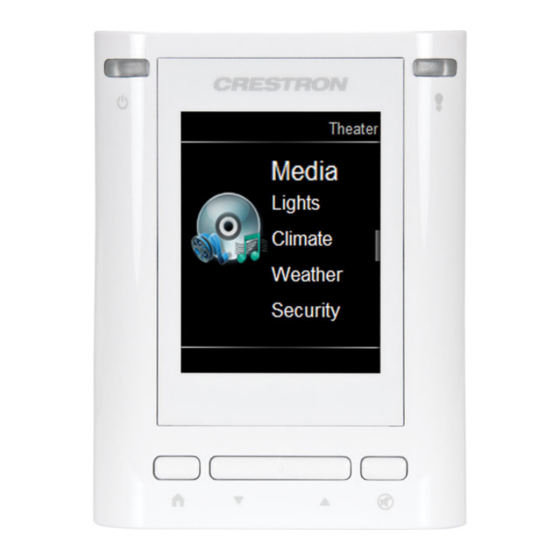
TPMC-3SM & TPMC-3SMD
2.8" Touch Screens
1
Install the Touch Screen
The Crestron
®
TPMC-3SM and TPMC-3SMD touch screens install into a standard electrical box.
Both are supplied with screws for installation.
To prepare for mounting, insert a small slot head screwdriver into the hole at the bottom of the
touch screen, shown in the illustration below and gently separate the back of the unit.
Insertion Point for Separation of Back Panel
Insert screwdriver to separate back of touch screen
To mount the TPMC-3SM or TPMC-3SMD into an electrical box, use the following procedure:
1. Use the two included screws to attach the back panel to the electrical box, as shown in
the following illustration.
For U.S.-style installations, use the #06-32 x 1 1/2" screws (2031703).
For European-style installations, use the #4B x 3/4" screws (2019088).
Mount the TPMC-3SM or TPMC-3SMD into an Electrical Box (U.S.-Style Electrical Box Shown)
Electrical Box
Back Panel
Screws (2)
For U.S.-style: #06-32 x 1 1/2" (2031703)
For European-style: #4B x 3/4" (2019088)
1
For Regulatory Compliance information, refer to the latest
version of Doc. 7237.
QUICKSTART DOC. 7238B (2031721, Sheet 1 of 2)
www.crestron.com
888.273.7876
04.13
Specifications subject to
change without notice.
2. When making connections to the TPMC-3SM and TPMC-3SMD, use Crestron power supplies for
Crestron equipment.
Apply power after all connections have been made.
Hardware Connections for the TPMC-3SM and TPMC-3SMD
LAN PoE :
10 BASE - T / 100 BASE - TX
Ethernet to LAN
NOTE: The included cable mount ferrite bead, FBLB-7 (2032427)
should be placed on the LAN cable in the electrical box.
3. Carefully position the front of the touch screen over the back panel and gently snap it into place.
4. Insert one of the included #04-40 x 1/4" screws into the bottom of the unit to secure the touch screen,
as shown in the illustration below.
For standard applications, use the Phillips screw (2007160).
For secure applications, use the security type Torx screw (2025312).
Secure the TPMC-3SM and TPMC-3SMD
Screw (1) #04-40 x 1/4"
Phillips (2007160) for standard applications
Security type Torx (2025312) for secure applications
201.767.3400
Advertisement
Table of Contents

Summary of Contents for Crestron TPMC-3SM
- Page 1 The Crestron ® TPMC-3SM and TPMC-3SMD touch screens install into a standard electrical box. 2. When making connections to the TPMC-3SM and TPMC-3SMD, use Crestron power supplies for Both are supplied with screws for installation. Crestron equipment. To prepare for mounting, insert a small slot head screwdriver into the hole at the bottom of the Apply power after all connections have been made.
- Page 2 2. Press hard keys 1, 2, 3 and 4, under the touch screen display, in sequence twice (i.e. press 1, 2, 3, 4, 1, 2, 3, 4) within a five second period. NOTE: For details on configuring the TPMC-3SM and TPMC-3SMD, refer to the latest version of the TPMC-3SM & TPMC-3SMD Configuration Guide (Doc.
- Page 3 2.8” Touch Screens Dimensions Pinout Reference TPMC-3SM & TPMC-3SMD Overall Dimensions (Front and Side Views) The only connector on the TPMC-3SM and TPMC-3SMD is the LAN PoE port. 0 . 57 in 3 . 38 in ( 15 mm )
- Page 4 Other trademarks, registered trademarks and trade names may be used in this document to refer to either the entities claiming the marks and names or their products. Crestron disclaims proprietary interest in the marks and names of others. Crestron is not responsible for errors in typography or photography.


Need help?
Do you have a question about the TPMC-3SM and is the answer not in the manual?
Questions and answers