
Related Manuals for Crestron Isys TPMC-9L


Summary of Contents for Crestron Isys TPMC-9L
- Page 1 Crestron TPMC-9L ® Isys 9” Wall Mount Touch Screen Operations & Installation Guide...
- Page 2 United States and/or other countries. Other trademarks and trade names may be used in this document to refer to either the entities claiming the marks and names or their products. Crestron disclaims any proprietary interest in the marks and names of others.
-
Page 3: Table Of Contents
Hardware Hookup ..................... 31 Recommended Cleaning.................... 32 Programming Software ......................33 Software Requirements for the PC ................33 Programming with Crestron SystemBuilder.............. 33 Programming with SIMPL Windows ................ 33 Programming with VisionTools ................36 Push Button Programming ..................40 Uploading and Upgrading......................41 Establishing Communication.................. -
Page 5: Isys 9" Wall Mount Touch Screen: Tpmc-9L
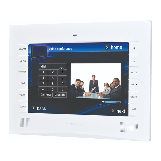
Introduction ® ® The Isys TPMC-9L Wall Mount Touch Screen from Crestron delivers high end style and performance in a compact, cost effective flush mount design. Featuring a generous 9” (~229 mm) widescreen display, advanced Core 3 UI™ touch screen graphics, high performance H.264 video and Rava™... - Page 6 Crestron TPMC-9L Advanced Touch Screen Control A Crestron touch screen offers an ideal user interface for controlling all the technology in a home, boardroom, classroom, courtroom or command center. Touch screens do away with piles of remote controls, cluttered wall switches and cryptic computer screens, simplifying and enhancing the technology.
- Page 7 Rava SIP Intercom Rava SIP Intercom technology enables hands free VoIP communication between any two Rava-enabled Crestron touch screens. Rava works over Ethernet, supporting 2-way intercom, video intercom*, paging and room monitoring without any special wiring. VoIP phone capability is also possible through integration with a...
-
Page 8: Applications
® Isys 9” Wall Mount Touch Screen Crestron TPMC-9L Applications The following diagram shows a TPMC-9L in a typical application. TPMC-9L in a Typical Application ® 4 • Isys 9” Wall Mount Touch Screen: TPMC-9L Operations & Installation Guide – DOC. 7030B... -
Page 9: Specifications
Streaming Formats H.264 (MPEG-4 part 10 AVC, MJPEG Audio Features Built-in microphone and speakers, Rava SIP Intercom, Crestron IP Intercom Audio Feedback WAV format, 8 & 16-bit PCM, 8 - 44.1 kHz sampling rates, mono & stereo Power Requirements Cresnet Power Usage 23 Watts (0.96 Amps @ 24 Volts DC) - Page 10 ® Isys 9” Wall Mount Touch Screen Crestron TPMC-9L TPMC-9L Specifications (Continued) SPECIFICATION DETAILS Environmental Temperature 32º to 112º F (0º to 45º C) Humidity 10% to 90% RH (non-condensing) Heat Dissipation 78 BTU/Hr Enclosure Construction Plastic, flush mountable using (4) clips...
- Page 11 Trim Ring 1. Refer to “Identity Code” on page 12 for details. 2. The latest software versions can be obtained from the Crestron Web site. Refer to the NOTE following these footnotes. 3. Crestron 2-Series control systems include the AV2 and PRO2. Consult the latest Crestron Product Catalog for a complete list of 2-Series control systems.
-
Page 12: Physical Description
® Isys 9” Wall Mount Touch Screen Crestron TPMC-9L Physical Description This section provides information on the connections, controls and indicators available on the TPMC-9L. TPMC-9L Physical View TPMC-9L Physical View (With No-Button Faceplate) ® 8 • Isys 9” Wall Mount Touch Screen: TPMC-9L... - Page 13 ® Crestron TPMC-9L Isys 9” Wall Mount Touch Screen TPMC-9L Overall Dimensions (Front and Side Views, with Faceplate) 1.86 in (48 mm) 0.38 in (10 mm) Light Sensor Microphone 0.39 in (10 mm) 7.52 in (191 mm) 10.83 in (275 mm) TPMC-9L Overall Dimensions (Front and Side Views) 10.69 in...
- Page 14 Input impedance: 100 Ω nominal; Input level: 1 V nominal, 1.5 V maximum; Maximum DC offset: ± 2 Volts; Connects to any Crestron CAT5 Video Out port ® via CresCAT or CAT5 cable VIDEO (UNBL) (1) 2-pin 3.5 mm detachable terminal block;...
- Page 15 ® Crestron TPMC-9L Isys 9” Wall Mount Touch Screen Connectors, Controls & Indicators (Continued) CONNECTORS, DESCRIPTION CONTROLS & INDICATORS (1) 4-pin 3.5 mm detachable terminal block; Cresnet slave port, connects to Cresnet control network Power (24 Volts DC) Data Data Ground (1) 8-wire RJ-45 with two LED indicators;...
-
Page 16: Setup
The IP ID is set within the TPMC-9L’s IP table using the internal setup menu (refer to “IP Table” which starts on page 16). IP ID may also be set from a PC via Crestron Toolbox. For information on setting an IP table, refer to the Crestron Toolbox help file. -
Page 17: Configuring The Touch Screen
® Crestron TPMC-9L Isys 9” Wall Mount Touch Screen Configuring the Touch Screen The TPMC-9L is configured from the setup menu. NOTE: The only connection required to configure the touch screen is power. Refer to “Hardware Hookup” which starts on page 31 for details. - Page 18 ® Isys 9” Wall Mount Touch Screen Crestron TPMC-9L Ethernet Touch Ethernet to enter the “Ethernet Setup Menu”, shown in the illustration below. “Ethernet Setup Menu” The “Ethernet Setup Menu” displays information about the Link Status, Control Connection, DHCP, MAC address, IP address, subnet, default gateway, primary DNS and secondary DNS.
- Page 19 ® Crestron TPMC-9L Isys 9” Wall Mount Touch Screen Numeric Keypad Touch CLEAR to remove any previous entry. Then enter the address required. Touch OK to accept the entry or CANCEL to cancel the entry. This hides the numeric keypad and returns the display to the “IP Address” screen.
- Page 20 ® Isys 9” Wall Mount Touch Screen Crestron TPMC-9L IP Table From the main “Setup” menu, touch IP Table to enter the “Control System Interface” menu, shown in the illustration below. “Control System Interface” Menu The “Control System Interface” menu contains buttons for eight IP Table slots as well as Add IP, Edit IP and Remove IP buttons to facilitate editing entries.
- Page 21 ® Crestron TPMC-9L Isys 9” Wall Mount Touch Screen Touch the IP Address / Hostname button. The on-screen keyboard opens, as shown in the illustration below. On-Screen Keyboard Touch CLEAR to remove any previous entry. Then enter the address required.
- Page 22 ® Isys 9” Wall Mount Touch Screen Crestron TPMC-9L Confirm IP Table Entry Removal By Pressing the OK Button, as shown in the illustration below. Confirm IP Table Entry Removal Screen Touch OK to confirm the removal or touch CANCEL to cancel the removal. The display returns to the “Control System Interface”...
- Page 23 ® Crestron TPMC-9L Isys 9” Wall Mount Touch Screen There is also a Restore Defaults button to return to factory settings and a window to display video. Touch the video window for a full screen video display, as shown in the illustration below.
- Page 24 ® Isys 9” Wall Mount Touch Screen Crestron TPMC-9L The “Audio Setup” screen contains buttons for adjustment or muting of Master Volume, Wave Volume, KeyClick Volume and Intercom Volume. There is also a Play Test Wave button. Touch Return to go back to the main “Setup” menu.
- Page 25 ® Crestron TPMC-9L Isys 9” Wall Mount Touch Screen Diagnostics From the main “Setup” menu, touch Diagnostics to enter the “Diagnostics” menu, shown in the illustration below. “Diagnostics” Menu The “Diagnostics” menu contains buttons for Test Patterns, Touch Test, Keypad Test, Swipe Test, Mic Test and Calibrate Touch.
- Page 26 ® Isys 9” Wall Mount Touch Screen Crestron TPMC-9L and Display White. From any of these, touch the screen to return to the “Touch Patterns” screen. From the “Touch Patterns” screen, touch Return to go back to the “Diagnostics” menu.
- Page 27 ® Crestron TPMC-9L Isys 9” Wall Mount Touch Screen The “Diagnostics – Keypad Test” screen allows testing of the hard keys on the touch screen faceplate (assuming the button faceplate and not the no-button faceplate is installed). Pressing any of the hard keys results in its corresponding section of the screen changing (from a black number on a white background to a white number on a dark background) in recognition of the key press.
- Page 28 ® Isys 9” Wall Mount Touch Screen Crestron TPMC-9L This screen performs a test of the TPMC-9L’s built-in microphone. The touch screen records audio for five seconds and then plays back the recorded sound. Speak into the microphone on the front of the TPMC-9L and the recording is played back to confirm the microphone is functioning.
- Page 29 ® Crestron TPMC-9L Isys 9” Wall Mount Touch Screen Screen Brightness Controls Use the Screen Brightness controls to adjust the relative level (0% to 100%) of current brightness. Use the Screen Brightness Level – HIGH and Screen Brightness Level – LOW controls to set the high and low preset brightness levels. Press the HIGH and LOW buttons to check each level.
- Page 30 ® Isys 9” Wall Mount Touch Screen Crestron TPMC-9L With the Auto Key Backlight Control set to Manual, the key backlighting is at the level set by the Keypad Backlight Brightness controls (which appear in place of the Sensor Threshold and Current Light Sensor Level meters, as shown in the illustration that follows).
-
Page 31: Mounting Options
® Crestron TPMC-9L Isys 9” Wall Mount Touch Screen Mounting Options The TPMC-9L installs simply and cleanly into existing or newly constructed walls, with an assortment of pre- and post-construction mounting options. The TPMC-9L is supplied with four screws and clips for post-construction installation. All available mounting options are listed in the following table. - Page 32 ® Isys 9” Wall Mount Touch Screen Crestron TPMC-9L Mounting Parts Supplied with the TPMC-9L PART DESCRIPTION PART NUMBER QUANTITY Metal Mounting Clip 2014237 Overlay Template Cutout 4511860 Connector Plug, 2-pin 2003574 Connector Plug, 3-pin 2003575 Connector Plug, 4-pin 2003576 Screw, #6-AB x 2-1/2”, Pan Head...
- Page 33 ® Crestron TPMC-9L Isys 9” Wall Mount Touch Screen TPMC-9L Cutout Dimensions (4511860, 2 of 2) 12 in 15/16 in (305 mm) (23 mm) TEMPLATE – OV40110 CUT ALONG FOR TPMC-9L MOUNTING CLIPS ONLY THIS EDGE 2 OF 2 3/16 in...
- Page 34 TPMC-9L squarely in the mounting surface. Do not over-tighten the screws. Installing the Faceplate Use the Crestron Engraver software package to obtain a custom-engraved faceplate for the TPMC-9L. Install the faceplate as follows. 1. Carefully position the faceplate over the face of the touch screen.
-
Page 35: Touch Screen Removal
Make the necessary connections as called out in the illustration on the following page. Refer to “Network Wiring” on page 12 before attaching the 4-position terminal block connector. Apply power after all connections have been made. When making connections to the TPMC-9L, use Crestron power supplies for Crestron equipment. ®... -
Page 36: Recommended Cleaning
® Isys 9” Wall Mount Touch Screen Crestron TPMC-9L Hardware Connections for the TPMC-9L (Front View) USB: Computer Hardware Connections for the TPMC-9L (Rear View) VIDEO: VIDEO: NET: LAN: From Balanced From Unbalanced To Control System and 10/100BASE-T Video Source... -
Page 37: Programming Software
Have a question or comment about Crestron software? Answers to frequently asked questions (FAQs) can be viewed in the Online Help section of the Crestron Web site. To post a question or view questions submitted to Crestron’s True Blue Support, log in at www.crestron.com/onlinehelp. First-time users must establish a user account to fully benefit from all available features. - Page 38 ® Isys 9” Wall Mount Touch Screen Crestron TPMC-9L Locating the TPMC-9L (Cresnet) in the Device Library b. To incorporate the TPMC-9L (Ethernet) into the system, drag the TPMC-9L from the Touchpanels | Touchpanels (Ethernet) folder of the Device Library and drop it in the System Views.
- Page 39 3. If necessary, double click a device to open the “Device Settings” window and change the Net ID or IP ID, as shown in the following illustrations. “Device Settings: Crestron TPMC-9L (Cresnet)” Window ® 9” Wall Mount Touch Screen: TPMC-9L • 35 Operations &...
-
Page 40: Programming With Visiontools
Net ID or IP ID of each unit. Refer to “Identity Code” on page Program Manager Program Manager is the view where programmers “program” a Crestron control system by assigning signals to symbols. The symbol can be viewed by double clicking on the icon or dragging it into Detail View. - Page 41 Pre-recorded WAV files for voice prompts and responses are available from Crestron. These files can be stored into and programmed for use in the touch screen directly or may be edited with the Sound Recorder. For example, the individual files can be combined to create custom messages.
- Page 42 ® Isys 9” Wall Mount Touch Screen Crestron TPMC-9L Relationship of Bits to Colors NUMBER OF BITS NUMBER OF COLORS 1 bit Black and White 2 bits 4 Colors 4 bits 16 Colors 8 bits 256 Colors 16 bits 65,536 Colors (Highcolor) 24 bits 16.7 million Colors (Truecolor)
- Page 43 ® Crestron TPMC-9L Isys 9” Wall Mount Touch Screen MultiByte International Characters Most languages use a single byte of eight bits to represent a character, e.g., English, French, German, Hebrew, Russian, Thai, etc. Multibyte character fonts require more than the usual eight bits to specify a character.
-
Page 44: Push Button Programming
® Isys 9” Wall Mount Touch Screen Crestron TPMC-9L Push Button Programming The twelve push buttons that flank the display can be programmed to access any frequently used command. Each button has a permanently fixed digital join number. The sequence of digital join numbers is (top to bottom, left to right) 1 through 6 and 7 through 12. -
Page 45: Uploading And Upgrading
2-Series Control Systems Reference Guide (Doc. 6256). 2. Use the Address Book in Crestron Toolbox to create an entry for the TPMC-9L using the expected communication protocol (Indirect). Select the Cresnet ID of the TPMC-9L and the address book entry of the control system that is connected to the TPMC-9L. - Page 46 Crestron Toolbox The USB port on the TPMC-9L connects to the USB port on the PC: 1. Use a USB cable to connect the TPMC-9L to a PC running the Crestron Toolbox. 2. Open the “System Info” window; click the “Enter an address …” icon (pencil) to display the “Edit Address”...
-
Page 47: Programs, Projects And Firmware
Crestron Toolbox. For details on uploading and upgrading, refer to the SIMPL Windows help file, VT Pro-e help file or the Crestron Toolbox help file. SIMPL Windows If a SIMPL Windows program is provided, it can be uploaded to the control system using SIMPL Windows or Crestron Toolbox. -
Page 48: Problem Solving
Isys 9” Wall Mount Touch Screen Crestron TPMC-9L Problem Solving Troubleshooting The following table provides corrective action for possible trouble situations. If further assistance is required, please contact a Crestron customer service representative. TPMC-9L Troubleshooting TROUBLE POSSIBLE CAUSE(S) CORRECTIVE ACTION... -
Page 49: Check Network Wiring
Cresnet power usage of the entire chain. If the unit is run from a Crestron system power supply network port, the Cresnet power usage of that unit is the Cresnet power usage of the entire run. The wire gauge and the Cresnet power usage of the run should be used in the following equation to calculate the cable length value on the equation’s left side. -
Page 50: Reference Documents
Crestron worldwide offices on the Crestron Web site (www.crestron.com/offices) for assistance within a particular geographic region. To post a question about Crestron products, log onto the Online Help section of the Crestron Web site (www.crestron.com/onlinehelp). First-time users must establish a user account to fully benefit from all available features. -
Page 51: Return And Warranty Policies
Crestron software, including without limitation, product development software and product operating system software is licensed to Crestron dealers and Crestron Authorized Independent Programmers (CAIPs) under a limited non-exclusive, non-transferable license pursuant to a separate end-user license agreement. The terms of this end user license agreement can be found on the Crestron Web site at www.crestron.com/legal/software_license_agreement. - Page 52 Crestron Electronics, Inc. Operations & Installation Guide – DOC. 7030B 15 Volvo Drive Rockleigh, NJ 07647 (2028354) Tel: 888.CRESTRON 08.12 Fax: 201.767.7576 Specifications subject to www.crestron.com change without notice.
Need help?
Do you have a question about the Isys TPMC-9L and is the answer not in the manual?
Questions and answers