Table of Contents
Advertisement
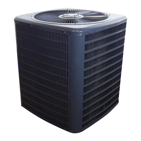
Service Instructions
Split System Air Conditioners,
Split System Heat Pumps
with R-22 Refrigerant
Blowers, Coils, & Accessories
This manual is to be used by qualified, professionally trained HVAC
technicians only. Goodman does not assume any responsibility for
RT6100004r13
property damage or personal injury due to improper service
May 2009
procedures or services performed by an unqualified person.
Copyright
© 2005 - 2009 Goodman
Manufacturing Company, L.P.
Advertisement
Table of Contents
Troubleshooting


Need help?
Do you have a question about the GSH Series and is the answer not in the manual?
Questions and answers