Table of Contents
Advertisement
Quick Links
Advertisement
Table of Contents

Related Manuals for Coemar par lite LED


Summary of Contents for Coemar par lite LED
- Page 1 lite manuale di istruzioni instructions manual Version 1.1...
- Page 2 Please note in the space provided above the relative service information of the model and the retailer from whom you purchased your Par Lite LED : this information will assist us in providing spare parts, repairs or in answering any technical enquiries with the utmost speed and accuracy.
-
Page 3: Table Of Contents
English Index 1. Packaging and transportation Pag. 4 1.1. Packaging “ 1.2. Transportation “ 2. General information Pag. 4 2.1. Important safety information “ 2.2. Warranty conditions “ 2.3. CE Certification “ 3. Product specifications Pag. 5 3.1. Technical characteristics “... -
Page 4: Packaging
2. For mains connection, adhere strictly to the guidelines outlined in this manual. 3. The level of technology inherent in the Par Lite LED requires the use of specialised personnel for all service applications; refer all work to your authorised Coemar service centre. -
Page 5: Technical Characteristics
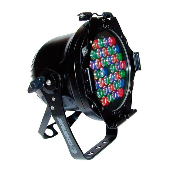
212mm 7.24” 8.35” 268mm 10.5” 3.3. Projector components The principal components of the Par Lite LED are shown in the diagram below. Descrizione dei componenti 1. Rear panel 2. Projector body 3. Dip-switch panel 4. Led control PCB 5. Switching power supply 6. -
Page 6: Mechanical Installation
Par Lite LED may be floor mounted or hung from an appropriate structure in any position. Permanent installation Use the three holes “A” on the yoke of the Par Lite LED for robust, permanent installation. Mobile installations If hanging the fixture from a lighting truss or similar, we recommend the use of appropriate clamps “B”, affixed to the yoke in the holes “A”... -
Page 7: Adjusting Beam Direction
4.2. Safety chain When hanging the Par Lite LED we recommend the use of a safety chain “C” affixed to the yoke and to the suspension device. The safety chain should be either a metal wire rope or a metal chain, both suitably rated for the purpose. -
Page 8: Opening And Closing Up The Projector
4.5. Adjusting the beam angle Several optional optical groups are available for Par Lite Led. They are used to vary the beam dimension and make it suitable for dif- ferent lighting applications and specifically: a group of lenses for a larger projection angle, a flood reflector and several filters that can be fitted either internally or externally to the unit The standard optical group, fitted on Par Lite Led, is composed by a group of lenses that gives 12°... - Page 9 To vary the wideness of the beam without opening the unit, it’ s possible to install an external filter holder “S” (code CO9169/1), as shown on following drawing. The following table details the range of beam angle and diffusion filters available for the Par Lite Led. Optical group...
-
Page 10: Operating Voltage And Frequency
• Prior to connecting the device to mains power, ensure that the mains characteristics are within the recommended range for use with the Par Lite Led. • A good earth connection is essential for the correcdt operation of the Par Lite Led. Never install the unit unless the yellow/gree earth cable is securely connected. -
Page 11: Connecting Dmx Signal
Control signal is digital and is transmitted via two pair screened cable, as recommended in international standards for the transmission of DMX512. Connection is serial, utilising the XLR3 sockets located on the rear panel of the Par Lite LED. Signal connection via the XLR3 connectors Connection is to international standards. -
Page 12: Dmx Addressing
IMPORTANT NOTE: the following points are valid for all the instructions which follow. 1. Setting a dip-switch to the ON position activates its function 2. The DMX address may be altered without the need to turn the Par Lite LED off. The following are examples only for setting DMX addresses. - Page 13 English 7. Test function With the dip-switch set to the ON position, Par Lite LED will test each individual channel without the need for a DMX controller to be connected. For example: set the dip-switch to ON on the Par Lite LED.
-
Page 14: Master/Slave Mode
9.1. MASTER/SLAVE mode In MASTER/SLAVE mode, it is possible to control, via a projector set as MASTER, a series of Par Lite LED units set to act as SLAVE fix- tures. The table below displays the settings required for fixtures to be connected in this manner. -
Page 15: Stand Alone Mode
1 8 16 32 64 128 To configure the Par Lite LED as STAND ALONE simply set dip-switch Auto to the ON position and select the program you wish to run and the hold and crossfade times to fol-... - Page 16 DMX signal. 10.1. IR MASTER/SLAVE mode In MASTER/SLAVE mode it is possible to control a fixture set as MASTER, and other Par Lite LED configured as SLAVES. The following diagram outlines the necessary settings for this configuration. MASTER IR...
-
Page 17: Dr1 Function
2) force leds on 3) function mode To initiate communications with the Par Lite LED the DR1 must be installed into the DMX signal chain between the fixture and the controller following the instructions located internally on the unit. The DR1 dip-switch must be set to the ON position; from this point on, dip-switches 1 to 128 take on the task of assigning an iden- tifying value (ID) to the fixture. - Page 18 11.1. Function modes using DR1 (MODE) Using the inbuilt functionality of the Par Lite LED via the DR1, it is possible to alter the function mode of the fixture. The following dia- gram illustrates the menu navigation system of the DR1 in MODE.
- Page 19 11.2. Setting up functionality via DR1 (FUNC) Using the inbuilt functionality of the Par Lite LED via the DR1, it is possible to alter the function settings of the fixture. The following diagram illustrates the menu navigation system of the DR1 in FUNC.
-
Page 20: Diagnostic Functions Using Dr1 (Meas)
The initial configuration settings are fautly or have been loaded incorrectly. The projector has loaded its default configuration. Turn the projector off and on again and if the error persists the EEPROM is either defective or absent; refer to your Coemar service centre for a replacement component. DMX ADDRESS Error ADER The projector is not receiving all the DMX channels necessary for its operation. -
Page 21: Periodic Maintenance
DMX OK connected 13. Thermal protection A thermal sensor in the body of the Par Lite LED protects the fixture against overheating. The sensor operates by removing power to the leds should the operating temperature exceed the factory preset. 14. Maintenance Whilst every possible precaution has been taken to ensure the trouble-free operation of your Par Lite LED, the following periodic main- tenance is highly recommended. -
Page 22: Frequently Asked Questions
- Par Lite LED may be incorrectly addressed. Check the DMX addres- sing. The Par Lite LED is set to auto but is not running any pro- In addtion to setting the AUTO dip-switch to on, it is necessary to also grams select a program number (see section 9. - Page 23 English Coemar s.p.a. via Inghilterra 2/A - 46042 Castel Goffredo (Mantova) Italy ph. +39 0376/77521 - fax +39 0376/780657 info@coemar.com Coemar si riserva il diritto di apportare modifiche senza preavviso. Coemar reserves the right to effect modifications without notification...
Need help?
Do you have a question about the par lite LED and is the answer not in the manual?
Questions and answers