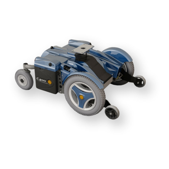
Permobil C400 Service Manual
Hide thumbs
Also See for C400:
- Service manual (132 pages) ,
- Owner's manual (84 pages) ,
- Assembly instruction manual (26 pages)
Table of Contents
Advertisement
Advertisement
Table of Contents

Related Manuals for Permobil C400


Summary of Contents for Permobil C400
- Page 1 SERVICE MANUAL Permobil C400 Power wheelchair...
- Page 3 Head Office of the Permobil group Permobil AB Box 120, 861 23 Timrå, Sweden Tel: +46 60 59 59 00. Fax: +46 60 57 52 50 E-mail: info@permobil.se Produced and published by Permobil AB, Sweden Edition no.7, 2009-06 Order no.: 205208-US-0...
-
Page 4: Table Of Contents
Contents Contents Introduction ...................... 5 Identification plates ..................6 Covers ....................... 8 Batteries ......................10 Front wheels ....................12 Rear wheels ....................14 Support wheels ....................15 Wheel forks ....................16 Rear wheel suspension ................. 17 Shock absorbers .................... 18 Slewing brackets ................... -
Page 5: Introduction
Permobil to ensure that the correct information is provided. Technical Support In the event of technical problems, you should contact your dealer, or Permobil Inc. USA at 800-736-0925. Spare parts Spare parts must be ordered through your dealer. -
Page 6: Identification Plates
Identification plates Identification plates Chassis Chassis identification number. Pilot+ controller Pilot+ controller identification number. Control panel Pilot+ Control panel Pilot+ identification number. - Page 7 Identification plates Control panel VSI Control panel VSI identification number.
-
Page 8: Covers
Covers Covers Removing the seat elevator cover 1. Raise the seat to the highest position. If the chassis is equiped with fixed seat post, see page 34. If the seat elevator does not work normally because the batteries are discharged or the actuator is defective, the seat can be raised/lowered manually, see page 30. - Page 9 Covers Covers Removing the front fender 1. Remove the three screws, see fig. 2. Remove the front fender by lifting it upwards/forwards. NOTE If the chair is equipped with lighting, remove the chassis- and seat elevator cover. Disconnect the front-light cabling at the connector fitted on the cabling.
-
Page 10: Batteries
Batteries Batteries WARNING Be careful when using metal objects when working with batteries. A short-circuit can easily cause an explosion. Always use safety gloves and safety goggles. Removal 1. Place the wheelchair on a level surface. 2. Switch off the main power switch on the control panel. - Page 11 Batteries Batteries Fitting 1. Lift new batteries into the chassis using the battery belt. Leave the battery belt on the batteries. Place the battery with the battery terminals facing backwards, see fig. WARNING Be careful when using metal objects when working with batteries.
-
Page 12: Front Wheels
Front wheels Front wheels Removal 1. Turn off the main power switch on the control panel. 2. Lift the wheelchair chassis and support it on blocks so that the wheel is off the ground. 3. Remove the hubcap (1), bolt (2) and the three washers (3 and 4);... - Page 13 Front wheels Front wheels Replacement of inner tube 1. Turn off the main power switch on the control panel. 2. Put the wheelchair up on blocks so that the wheel is free and then let the air out of it. 3.
-
Page 14: Rear Wheels
Rear wheels Rear wheels Removal 1. Turn off the main power switch on the control panel. 2. Lift the wheelchair chassis and support it on blocks so that the wheel is off the ground. 3. Remove the hucap (1). 4. Remove the screw (2) and the washer (3). 5. -
Page 15: Support Wheels
Support wheels Support Wheels The support wheels should always be fitted in the upper position, see fig. Removing the support wheels 1. Turn off the main power switch on the control panel. 2. Remove the bolt, see fig. WARNING Removing the support wheels entails an increased risk of the wheelchair tipping over. -
Page 16: Wheel Forks
Wheel Forks Wheel Forks Removal 1. Switch off the main power switch on the control panel. 2. Lift up and chock up the wheelchair chassis so that the wheel in question is free of the ground. 3. Remove the cap from the top of the link arm. See fig. -
Page 17: Rear Wheel Suspension
Rear wheel suspension Rear wheel suspension Removal 1. Switch off the main power switch on the control panel. 2. Lift up and chock up the wheelchair chassis so that the rear wheel suspension is free of the ground. 3. Remove the rear wheel suspension. It is fitted with a bolt with two washers, see fig. -
Page 18: Shock Absorbers
Shock Absorbers Shock Absorbers Removal 1. Switch off the main power switch on the control panel. 2. Remove the front fender on the side in question, see page 9. 3. Lift up and chock up the wheelchair chassis so that the wheel in question is free of the ground. 4. - Page 19 Shock Absorbers Shock Absorbers Adjustment Before the new shock absorber is mounted, it must be adjusted to the proper value. The spring force can be set to suit different user weights using the adjustment nut. Increase the dimension fo a harder suspension, decrease the dimension for a softer suspension, see fig. below. NOTE Make sure using the right settings for the right shock absorber.
-
Page 20: Slewing Brackets
Slewing brackets Slewing brackets Removal 1. Raise the seat to the highest position. If the chassis is equiped with fixed seat post, see page 34. If the seat elevator does not work normally because the batteries are discharged or the actuator is defective, the seat can be raised/lowered manually, see page 30. - Page 21 Slewing brackets Slewing brackets 9. Remove the slewing bracket, it is fitted with screw and washer. For removal of the drive motor, see page 28. Fitting Fit the slewing brackets in the reverse order. Tighten the bolt holding the wheel fork in place with a torque wrench.
-
Page 22: Wheel Lock Release Cable
Wheel lock release cable Wheel lock release cable Removal 1. Raise the seat to the highest position. If the chassis is equiped with fixed seat post, see page 34. If the seat elevator does not work normally because the batteries are discharged or the actuator is defective, the seat can be raised/lowered manually, see page 30. - Page 23 Wheel lock release cable Wheel lock release cable Fitting 1. Fit the cable at the magnetic wheel lock first, then at the release lever. 2. Adjust the cable sleeve length with the adjusting screw (2) so that the cable is sufficiently tensioned so that the wheel lock release sensor (see figure) is actuated just before the cable pulls the release.
-
Page 24: Wheel Lock Release Sensor
Wheel lock release sensor Wheel lock release sensor Removal 1. Switch off the main power switch on the control panel. 2. On wheelchairs with Pilot+ control system, put the circuit breaker in the “OFF” position. It is accessed through a hole in the chassis cover; see page 41. -
Page 25: Magnetic Wheel Lock
Magnetic wheel lock Magnetic wheel lock Removal 1. Raise the seat to the highest position. If the chassis is equiped with fixed seat post, see page 34. If the seat elevator does not work normally because the batteries are discharged or the actuator is defective, the seat can be raised/lowered manually, see page 30. - Page 26 Magnetic wheel lock Fitting 1. Using the adjusting screws, adjust the magnet wheel lock in accordance with the instructions on the back of the magnetic wheel lock; see fig. Wheel lock adjustment is made using the two adjusting screws. Magnetic wheel lock, wheel lock disk, cover and rubber seal disassembled.
- Page 27 Magnetic wheel lock 4. Insert a screw to align the parts. Attach the rubber seal with the drainage hole down. Be attentive to the position of the wheel lock release lever; fit the wheel lock so that the wheel lock release lever is aligned with the motor’s cable bracket.
-
Page 28: Drive Motor
Drive motor Drive motor Removal 1. Raise the seat to the highest position. If the chassis is equiped with fixed seat post, see page 34. If the seat elevator does not work normally because the batteries are discharged or the actuator is defective, the seat can be raised/lowered manually, see page 30. - Page 29 Drive motor Drive motor 9. Remove the drive motor. It is attached with three screws; see fig. Fitting Fit the drive motor in the reverse order. Drive motor mounting screws. Drive motor with gear.
-
Page 30: Seat Elevator
Seat elevator Seat elevator Manual Raising/ Lowering of the Seat elevator If the seat elevator does not work normally because the batteries are discharged or the actuator defective, seat raised/lowered manually. 1. Switch off the main power switch on the control panel. -
Page 31: Removing The Seat Elevator
Seat elevator Seat elevator Removal 1. Raise the seat to the highest position. If the seat elevator does not work normally because the batteries are discharged or the actuator is defective, the seat can be raised/lowered manually, see page 30. 2. -
Page 32: Seat Elevator Cable
Seat elevator cable & Seat elevator motor Seat elevator cable Removing 1. Remove the seat elevator; follow the instructions on page 31. 2. Remove the seat elevator sensors. Note the position of the sensors for refitting, see fig. Fitting Fitting is the reverse procedure. Attachment of the sensors to the seat elevator. -
Page 33: Seat Elevator Drive Belt
Seat elevator drive belt Seat elevator drive belt Removing 1. Remove the seat elevator, see page 31. 2. Loosen the two bolts holding the shaft to the seat elevator motor. Push the shaft sideways to slacken the drive belt. 3. Remove the belt from the motor shaft, then from the toothed wheel on the seat elevator screw. -
Page 34: Fixed Seat Post
Fixed seat post Fixed seat post Adjusting the Seat Height The length of the fixed seat post can be adjusted to five different fixed positions. 1. Switch off the main power switch on the control panel. 2. Loosen the screw that locks the fixed height position of the seat post. -
Page 35: Removal
Fixed seat post Fixed seat post Removal 1. Switch off the main power switch on the control panel. 2. On wheelchairs with Pilot+ control system, put the circuit breaker in the “OFF” position. It is accessed through a hole in the chassis cover; see page 41. -
Page 36: Control Panel Pilot
Control panel Pilot+ Control panel Pilot+ Removal Switch off the main power switch on the control panel. Disconnect the control panel cable by pulling the connector at the rear of the control panel straight backwards. To remove the control panel, remove the screws holding the common bracket for the control panel and Seat control panel, see figure. -
Page 37: Control Panel Vsi
Control panel VSI Control panel VSI The VSI control panel is a unit that, in addition to a joystick and control buttons, also contains all other electronics required, including a controller. The control panel and complete cabling are replaced as one unit. Removal 1. -
Page 38: Pilot+ Controller
Slutsteg Pilot+ Pilot+ controller (Pilot+ only) Removal 1. Raise the seat to the highest position. If the chassis is equiped with fixed seat post, see page 34. If the seat elevator does not work normally because the batteries are discharged or the actuator is defective, the seat can be raised/lowered manually, see page 30. -
Page 39: Sls Drive Stage
SLS Drive Stage SLS Drive Stage (Pilot+ only) Removal 1. Raise the seat to the highest position. If the chassis is equiped with fixed seat post, see page 34. If the seat elevator does not work normally because the batteries are discharged or the actuator is defective, the seat can be raised/lowered manually, see page 30. -
Page 40: Fuses
Circuit breaker and fuses Circuit breaker and fuses Main Fuse (VSI) The main fuse is located under the chassis cover behind the seat elevator/fixed seat post. NOTE If the main fuse blows, there is often a major electrical fault. The cause of the fault should be checked carefully before the fuse is replaced. - Page 41 Circuit breaker and fuses Circuit breaker and fuses Resetting the circuit breaker (Pilot+) The circuit breaker also serves as a battery isolator but is normally referred to as a circuit breaker. Circuit breaker replacement is normally not required; it is of the automatic type that can be reset when tripped. NOTE A tripped circuit breaker often entails a major electrical fault.
-
Page 42: Sls- Fuse (Pilot+)
Circuit breaker and fuses Circuit breaker and fuses Replacing the SLS Fuse (Pilot+ only) The SLS fuse is located in its holder on the top of the left battery. 1. Switch off the main power switch on the control panel. 2. -
Page 43: Fuse For Seat/Lighting (Pilot+)
Circuit breaker and fuses Circuit breaker and fuses Replacing Fuses for the Seat/Lighting (Pilot+ only) There are two fuses on the SLS Drive stage, F1 (24V unswitched) and F2 (24V switched). These protect two outlets. One output (24V unswitched) supplies power regardless of if the chair is turned on or off. -
Page 44: Lights
Lights Lights (Accessories, Pilot+ only) Removing the front lights 1. Switch off the main power switch on the control panel. 2. Put the circuit breaker in the “OFF” position. It is accessed through a hole in the chassis cover; see page 41. 3. - Page 45 Lights Lights (Accessories, Pilot+ only) Removing the rear lights 1. Switch off the main power switch on the control panel. 2. Put the circuit breaker in the “OFF” position. It is accessed through a hole in the chassis cover; see page 41. 3.
-
Page 46: Control System
The control system can also be programmed in order to make adjustments needed for a specific user. To get more information about standard parameter files, contact your dealer, or Permobil Inc. USA. The chart below shows the different standard parameter files that are available. -
Page 47: Trouble Shooting
The troubleshooting guide below describes a number of events that can arise when you use your wheelchair, as well as providing suggestions for solutions. Note that this guide does not describe all the possible events that can arise, and you should always get in touch with your service contact or Permobil when you are unsure... - Page 48 Trouble Shooting Guide Error signals - Battery voltage indicator Every time the wheelchair is started up, a check is performed on parts of the wheelchair’s electronics. If any faults have arisen in these parts, this is shown on the control panel’s battery voltage indicator by one or more blinking lights.
- Page 49 Trouble Shooting Guide CAUSE SOLUTION Check the battery and the connections between the High battery voltage battery and the control unit. Green Failure in wheel lock circuit Check the connections to the magnetic wheel lock. Green Check the contacts to the output stage. If the fault Fault in electronics persists, change the output stage.
-
Page 50: Cabling Overview Vsi
Cabling overview... - Page 51 Cabling overview Cabling overview VSI...
-
Page 52: Cabling Overview Pilot
Cabling overview... - Page 53 Cabling overview Cabling overview Pilot+...
-
Page 54: Distribution Chart Vsi
Distribution chart... - Page 55 Distribution chart Distribution chart VSI...
-
Page 56: Distribution Chart Pilot
Distribution chart... - Page 57 Distribution chart Distribution chart Pilot+...
- Page 58 Notes...
- Page 59 Notes...
- Page 60 Notes...
-
Page 61: Index
Index Index Batteries ..........10 Magnetic wheel lock ......25 Cabling overview Pilot+ ....52 Pilot+ controller ......38 Cabling overview VSI ......50 Circuit breaker ........41 Control panel Pilot+ ......36 Rear wheels ........14 Control panel VSI ......37 Rear wheel suspension .... - Page 64 Order no.: 205208-US-0...
Need help?
Do you have a question about the C400 and is the answer not in the manual?
Questions and answers
déposer les batteries