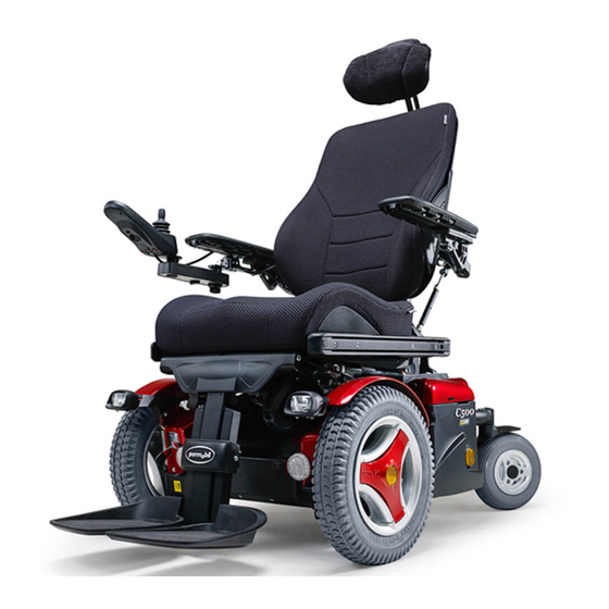
Permobil C500 Owner's Manual
Power wheelchair
Hide thumbs
Also See for C500:
- Owner's manual (100 pages) ,
- Service manual (68 pages) ,
- Assembly instruction manual (26 pages)
Table of Contents
Advertisement
Quick Links
Advertisement
Table of Contents

Related Manuals for Permobil C500


Summary of Contents for Permobil C500
- Page 1 Owner´s Manual Permobil C500 Permobil C500 Power Wheelchair...
- Page 3 Permobil Inc. USA 300 Duke Drive Lebanon, TN 37090 Phone: 800-736-0925 Fax: 800-231-3256 Email: info@permobilusa.com Head Office of the Permobil group Permobil AB Box 120 861 23 Timrå Sweden Tel: +46 60 59 59 00 Fax: +46 60 57 52 50...
- Page 4 Permobil C500 Power Wheelchair Produced and published by Permobil AB, Sweden Version no.: 7 - 2011-11 Art. no.: 205226-US-0...
-
Page 5: Table Of Contents
Permobil C500 Owner´s Manual Contents Important information about the owner´s manual ................6 General information ......................... 7 Technical support ........................7 Spare parts & accessories ....................... 7 Disposal ........................... 7 Warranty & service ........................7 Product approval ........................7 Safety rules ..........................8-23 Design &... -
Page 6: Important Information About The Owner´s Manual
It is also possible to obtain information concerning our products from our home page on the Internet. You can find us at www.permobil.com. All information, pictures, illustrations and specifications are based upon the product information that was available at the time that these operating instruc- tions were printed. -
Page 7: General Information
Permobil C500 Owner´s Manual Technical support, warranty, etc. TECHNICAL SUPPORT In the event of technical problems, you should contact your dealer or Permobil Inc USA at 1-800-736-0925. Always state the chassis serial number when contacting Permobil to ensure that the correct information is provided. -
Page 8: Safety Rules
Permobil is not responsible for personal injuries or property damage resulting from any person’s failure to follow the warnings and instructions in this manual. Permobil is not responsible for injuries or damage resulting from failure to exer- cise good judgment. - Page 9 • that all products ordered are included in the delivery, incuding operating instructions and possible other documentation. If you suspect that something is missing, then contact your supplier or Permobil for more information as soon as possible. • that no transport-related or other damages have occurred to the wheelchair and its accessories.
-
Page 10: Safety Instructions
Safety Instructions WARNING Operation Permobil recommends the use of wheelchair lights at all times user is riding near public rights of way. Use extreme caution when driving near unprotected ledges, drop-offs or on elevated surfaces. Unintended movement or excessive speed in these areas can lead to personal injury or property damage. - Page 11 Permobil products. Weight Limitations The maximum user weight for your Permobil is set forth in the specification section of the supplied Owner´s Manual for current seat model. Operation of the wheelchair by users who exceed the maximum allowable user weight can lead to personal injury and property damage, including damage to the wheel- chair, as well as voiding any applicable warranty to the wheelchair.
- Page 12 Permobil C500 Owner´s Manual Safety rules Safety Instructions CAUTION Operation - Inclines When driving downhill, select the slowest speed and proceed with caution. Driving down an incline in a front wheel drive wheelchair can shift the user’s center of gravity forward. If the wheelchair rolls faster than you would like, stop the wheelchair by releasing the joystick and begin descending again at a slower speed.
- Page 13 Permobil C500 Owner´s Manual Safety rules Safety Instructions WARNING Operation - Inclines Do not drive the wheelchair where the sideways gradient is more than indicated in the technical specifications section of the manual. There is a risk of tipping over.
- Page 14 In order to prevent the wheelchair from rolling away, ensure that the wheelchair is on a level and dry surface before releasing the brakes. In order to avoid personal injury do not use your Permobil in freewheel mode without an attendant present. Do not attempt to put the wheelchair in freewheel mode by yourself while seated in it.
- Page 15 Driving in Extreme Climate Conditions Permobil’s wheelchairs are designed to withstand most adverse weather con- ditions, however to minimize the risk of being caught in difficult situations you should avoid using the wheelchair outdoors during, for example, severe cold, heavy rain or thick snow.
- Page 16 Permobil C500 Owner´s Manual Safety rules Safety Instructions WARNING Driving with Seat Lift/Seat Tilt/Backrest Recline Be careful in making sure that nothing gets stuck between the chassis and the seat when the seat lift/seat tilt is operated. Operating the seat lift,seat tilt/ backrest recline changes the center of gravity and increases the risk of tipping over.
- Page 17 Overextending this distance can cause user to over- exert, lose balance, or fall. Permobil recommends that users transfer in the presence of or with the assis- tance of an attendant. Use caution when bending or reaching.
-
Page 18: Environmental Conditions
Permobil C500 Owner´s Manual Safety rules Safety Instructions WARNING Passengers The wheelchair is not intended to transport passengers, regardless of the age of the passenger. The Maximum User Weight stated in the Owner’s Manual for your seating includes the user and any personal effects. The Maximum limit should not be exceeded. - Page 19 Use Prohibited in Motor Vehicles Permobil recommends that users NOT be transported in any kind of vehicle while in their wheelchair, unless the user is in an approved Permobil wheel- chair configuration, has secured the wheelchair using a Permolock C, and is using a seatbelt attached to the vehicle.
- Page 20 Failure to do so can lead to personal injury. Do not use parts or accessories not authorized by Permobil. Use of unap- proved ”aftermarket” accessories and parts may cause changes in the wheel- chair, which may make the wheelchair unstable or uncontrollable.
- Page 21 Safety Instructions WARNING Safety Circuits Permobil products are equipped with safety circuits. Inhibit circuits prevent the wheelchair from driving under certain conditions. Speed reduction circuits limit the wheelchair’s maximum speed under certain conditions. Limit switch circuits limit the wheelchair’s functions under certain circumstances. Overload protec- tion circuits shut the wheelchair off in case of an overload.
- Page 22 Permobil and tighten the bolt to the recommended torque. Also, inspect the drive axle and wheel rim for any damage. Damage to either part can cause the wheel bolt to loosen or fracture. Permobil recommends that wheel bolts be used only one time.
- Page 23 The limit values for Electromagnetic Compatibility (EMC) with respect to elec- trical wheelchairs is set in the harmonized standards for the EU in the Medical Devices Directive, No. 93/42/EEC. Permobil’s electronic wheelchair’s comply with these limit values. Also see Important Information about Electromagnetic Interference (EMI) on page 73-74.
-
Page 24: Design & Function
Design and function Design & Function General The Permobil C500 is an electric front-wheel drive wheelchair for outdoor and indoor driving. It is intended for people with physical disabilities. The wheelchair consists of a chassis and a seat. The chassis contains the wheelchair’s electronics, power supply and drive functions. -
Page 25: Seat Lift Seat Angle
Permobil C500 Owner´s Manual Design and function Seat The Permobil C500 can be combined with different seat models, which are sup- plied with a separate owner´s manual. Seat lift The Permobil C500 can be fitted with an electrically controlled seat lift that allows the seat to be raised steplessly up to 7 3/4”... -
Page 26: Driving - Shock Absorbers
Adjustment of the spring force The adjustment should be performed by personnel who are very familiar with the design and function of the shock absorbers. If adjustment is required, please contact your nearest service engineer/service center or Permobil service. Shock absorbers... -
Page 27: Wheels, Lights, Reflectors
Permobil C500 Owner´s Manual Design and function Wheels The wheelchair’s front wheels, the drive wheels, have pneumatic tires. The rear wheels, the steering wheels, may have pneumatic or solid rubber tires. Lights and reflectors In the standard version, the wheelchair is fitted with reflectors at the front and rear and on the sides. -
Page 28: Electronics Batteries
Permobil C500 Owner´s Manual Design and function Electronics Batteries The wheelchair’s two batteries are located under the rear chassis cover and are easily accessible for maintenance and replacement. Position of the batteries WARNING Be careful when using metal objects when working with batteries. A short-circuit can easily cause an explosion. -
Page 29: Electronics - Fuses
Fuses/charging socket Main fuse/battery isolator The Permobil C500 is fitted with a 63 A or 80 A automatic main fuse that can be reset when it has been triggered. It also functions as a battery isolator and is controlled (ON/OFF) via the lever located above the left battery cover. -
Page 30: R-Net Control Panel Lcd Monochrome Display
Permobil C500 Owner´s Manual Design and function R-Net control panel LCD monochrome display General The Control Panel consists of a joystick, function buttons and a display. At the front of the panel is the Charger Socket. Two Jack Sockets are located on the bottom of the panel. -
Page 31: Charger Socket
Permobil C500 Owner´s Manual Design and function R-Net control panel LCD monochrome display Charger Socket This socket should only be used for charging or locking the wheelchair. Do not connect any type of programming cable into this socket This socket should not be used as a power supply for any other electrical device. - Page 32 Permobil C500 Owner´s Manual Design and function R-Net control panel LCD monochrome display Function keys There are a total of 10 function keys on the control panel. Horn On/Off Max. speed Reduce/Increase Profile Mode Lights* Hazard lights* Indicators* Indicators, left* * Applies only if the wheelchair is fitted with lights.
- Page 33 Permobil C500 Owner´s Manual Design and function R-Net control panel LCD monochrome display Mode The user can use the Mode key to scroll between the control system’s available modes. The available modes depend on the programming and on which other output devices are connected to the control system.
- Page 34 Permobil C500 Owner´s Manual Design and function R-Net control panel LCD monochrome displayl Socket for external on/off key You can use this socket to activate and deactivate the control system with an external device. Socket for external profile key (applies if profiles are programmed and used).
-
Page 35: Battery Indicator
Permobil C500 Owner´s Manual Design and function R-Net control panel LCD monochrome display Display By looking at the control panel display, you can get an idea of the status of the control system. The control system is active when the screen is lit. - Page 36 Permobil C500 Owner´s Manual Design and function R-Net control panel LCD monochrome display Speed Indicator This displays the current speed setting. The speed setting is adjusted using the Speed Buttons. Current Profile The Profile Number describes wich Profile the con- trol system is currently operating in.
- Page 37 Permobil C500 Owner´s Manual Design and function R-Net control panel LCD monochrome display Fault The control system can detect a wide variety of errors. When the system has detected an error that is not severe enough to cause the system to trip, then this symbol will be displayed.
-
Page 38: R-Net Control Panel Lcd Color Display
Design and function Permobil C500 User Manual R-Net control panel LCD color display General The Control Panel consists of a joystick, function buttons and a display. At the front of the panel is the Charger Socket. Two Jack Sockets are located on the bottom of the panel. - Page 39 Design and function Permobil C500 User Manual R-Net control panel LCD color display Charger Socket This socket should only be used for charging or locking the wheelchair. Do not connect any type of programming cable into this socket This socket should not be used as a power supply for any other electrical device.
-
Page 40: Function Buttons
Design and function Permobil C500 User Manual R-Net control panel LCD color display Function Buttons On the control panel there are a total of 10 Function Buttons. Horn Button On/Off Speedbuttons, Decrease/ PROFILE MODE Increase Profile Button Mode Lights Button & LED*) Hazard Button &... - Page 41 Design and function Permobil C500 User Manual R-Net control panel LCD color display Mode Button The Mode button allows the user to navigate through the available operating Modes for the control system. The available modes are dependant on program- ming and the range of auxiliary output devices connected to the control system.
- Page 42 Design and function Permobil C500 User Manual R-Net control panel LCD color display External On/Off Switch Jack This allows the user to turn the control system on and off using an external ability switch, such as a buddy button. External Profile/Mode Switch Jack (This jack’s function varies depending on the programming.)
- Page 43 Design and function Permobil C500 User Manual R-Net control panel LCD color display Display The status of the control system is shown in the display. The control system is on when the display is backlit. Screen Symbols The Drive screen for the R-net has common components, which will always appear, and components which will only appear under certain conditions.
- Page 44 Design and function Permobil C500 User Manual R-Net control panel LCD color display Speed Indicator This displays the current speed setting. The speed setting is adjusted using the Speed Buttons. Current Profile The Profile Number describes wich Profile the con- trol system is currently operating in.
- Page 45 Design and function Permobil C500 User Manual R-Net control panel LCD color display Motor Temperature This symbol is displayed when the control system has intentionally reduced the power to the motors, in order to protect them against heat damage. Control system Temperature...
- Page 46 Design and function Permobil C500 User Manual R-Net control panel LCD color display Installation menu The installation menu permits the user to set the clock, the display brightness, background color etc. Access the menu by holding down the keys for higher and lower maximum speed simultaneously.
- Page 47 Design and function Permobil C500 User Manual Control panel R-Net LCD color display Distance measurement (Distance) Select “Distance” in the menu. Move the joystick to the right to go to the menu for setting distance measurement. Then select “Total distance”, “Trip”, “Distance display”...
-
Page 48: R-Net Control Panel Led
Design and function Permobil C500 User Manual R-Net control panel LED General The Control Panel consists of a joystick, function buttons and a display. At the front of the panel is the Charger Socket. Two Jack Sockets are located on the bottom of the panel. - Page 49 Design and function Permobil C500 User Manual R-Net control panel LED Charger Socket This socket should only be used for charging or locking the wheelchair. Do not connect any type of programming cable into this socket This socket should not be used as a power supply for any other electrical device.
- Page 50 Design and function Permobil C500 User Manual R-Net control panel LED Function keys There are a total of 9 function keys on the control panel with LEDs. Battery voltage indicator Horn On/Off Mode Seat indicator Max. speed/profile Lights* Hazard lights* indicator Max.
- Page 51 Design and function Permobil C500 User Manual R-Net control panel LED Mode With the Mode key the user can scroll between the control system’s available operating modes. The available modes depend on the programming and on which other output devices are connected to the control system.
- Page 52 Design and function Permobil C500 User Manual R-Net control panel LED Battery voltage indicator Shows the voltage remaining in the batteries (from left to right): Red+Yellow+Green = Fully charged Red+Yellow = Half charged = Charge the batteries A good way of using this indicator is to learn how it works while you are driv- ing.
- Page 53 Design and function Permobil C500 User Manual R-Net control panel LED Max. speed indicator Speed Indicates the maximum speed set for the wheelchair. 2 lamps = Low speed 4 lamps = Average speed 5 lamps = Max. speed Driving profile For special applications, the wheelchair can be programmed with more than one driving profile.
- Page 54 Design and function Permobil C500 User Manual R-Net control panel LED Seat indicator On certain seats the electrical functions for seat lift, seat angle, backrest angle and legrest angle are controlled with the control panel joystick. In this case the active seat function is indicated on the control panel seat indicator.
-
Page 55: Operation
Permobil C500 User Manual Operation General The Permobil C500 is designed for use both indoors and outdoors. When you drive indoors, you must be careful in, for example, narrow passages, when going through doors and entrances and when using lifts, ramps, etc. -
Page 56: Joystick Error
Operation Permobil C500 User Manual Joystick Error If the joystick is moved from the central position before, during or immediately after the control system is switched on, the screen image for a shifted joystick will be displayed for 5 seconds. On control panels without a display, the LEDs on the battery voltage indicator will “wander”... -
Page 57: Driving Technique
Operation Permobil C500 User Manual Driving Technique The control system electronics “interpret” the movements of the joystick and move the wheelchair as intended. For normal driving, the user doesn’t need to employ any complex techniques, which is an advantage if the user is inexperienced. A good way of starting is quite simply to move the joystick in the direction you want to go. - Page 58 Permobil C500 Owner´s Manual Operation R-Net control panel Locking/unlocking the wheelchair The control system can be locked in two different ways. Either by using a key sequence on the keypad or with a physical key. The method used depends on how the system has been programmed.
- Page 59 Permobil C500 Owner´s Manual Operation R-Net control panel Locking with a key • Press the on/off key if the control system is switched off. • Insert and remove the key from the charging contact on the control panel. • The wheelchair is now locked.
-
Page 60: Seat Functions
Operation Permobil C500 User Manual Seat functions R-Net LCD (Not applicable to all seat models) On some seats the electrical functions can be controlled with the help of the control panel joystick. Some models are equipped with three memory locations. - Page 61 Operation Permobil C500 User Manual Seat functions R-Net LCD (Not applicable to all seat models) Return to drive mode Press the “Mode” button one or more times until a standard display image with speed indicator appears in the control panel display - see illustration.
- Page 62 Operation Permobil C500 User Manual Seat functions R-Net LCD (Not applicable to all seat models) The control system on some seats has three memory locations for seat pos- itions. Each memory location can store the position of the seat’s adjustment device.
- Page 63 Operation Permobil C500 User Manual Seat functions R-Net LCD (Not applicable to all seat models) Saving position to memory 1. Set the seat’s electrical functions to the desired mode. 2. If not activated, activate the seat/ memory function by pressing the “Mode”...
- Page 64 Permobil C500 Owner´s Manual Operation Seat functions R-Net LED (Not applicable to all seat models) On certain seats the electrical functions for seat lift, seat angle, backrest angle and legrest angle are controlled with the control panel joystick. Other seat functions require a separate seat con- trol panel.
- Page 65 Permobil C500 Owner´s Manual Operation Seat functions R-Net LED (Not applicable to all seat models) Return to drive mode Press the “Mode” button one or more times until a standard display image with speed indicator appears in the control panel display - see illustration.
-
Page 66: Driving Rules
Permobil C500 Owner´s Manual Operation Driving rules Support wheels Your wheelchair may be fitted with front support wheels to reduce the risk of tipping when driving over obstacles, etc. They must always be fitted when you drive. Front support wheels WARNING If your wheelchair is fitted with support wheels, they must always be fitted when you drive. -
Page 67: Driving Over Obstacles
Permobil C500 Owner´s Manual Operation Driving over obstacles Do not drive the wheelchair over obstacles higher than 3 inches. If you drive over higher edges, there is a higher risk of tipping and of damage to the wheelchair. You should always drive over obstacles with great caution. - Page 68 Permobil C500 Owner´s Manual Operation Driving downhill You should always drive downhill at low speed and with great caution. Avoid braking suddenly and sudden evasive maneuvers and never drive so fast that you are unable to control the wheelchair safely without risks.
- Page 69 Permobil C500 Owner´s Manual Operation Driving uphill You should always drive uphill with great caution. Avoid sudden evasive maneuvers and never drive so fast that you are unable to control the wheelchair safely without risks. You should be extremely careful when driving uphill on an uneven surface (for example grass, gravel, sand, ice and snow).
- Page 70 Permobil C500 Owner´s Manual Operation Driving on side slopes You should always drive on side slopes with great caution. Avoid sudden evasive maneuvers and never drive so fast that you are unable to control the wheelchair safely without risks. You should be extremely careful when driving on side slopes with an uneven surface (for example grass, gravel, sand, ice and snow).
-
Page 71: Manual Brake Release
Always reset the brake release after moving the wheelchair manually. When the brakes are released, it should not be possible to drive the chair. If the chair can still be driven, contact your service contact or Permobil immediately. -
Page 72: Charging Batteries
WARNING Use only the charger supplied with your wheelchair or recommended by Permobil. Using other chargers may damage the batteries, the wheelchair electronics or the charger itself. It may also result in parts becoming overheated, which may entail a greater risk of fire. -
Page 73: Charging Socket
Permobil C500 Owner´s Manual Operation Charging Ensure that the wheelchair is switched off with the On/Off key on the control panel and then connect the charging plug to the wheelchair’s charging socket. The battery voltage indicator on the wheelchair’s control panel lights up and shows the charging status during charging. -
Page 74: Transport
If your wheelchair is fitted with a luggage basket (accessory), it may be difficult, in some cases, to anchor the wheelchair in the rear transport eyes. This can be solved by ordering an additional pair of rear transport brackets. Contact Permobil for order information for these brackets. - Page 75 In an accident or sudden stop, you may be thrown from the chair and seriously injured or killed. Permobil positioning belts are designed to position the user only and not to protect you in the event of a motor vehicle accident. The positioning belts do not replace use of a vehicle mounted...
-
Page 76: Air Transport
Always check with the airline what rules apply. CAUTION If you do not know what type of main fuse your wheelchair has, contact Permobil or your service contact. Some airlines may refuse to accept acid batteries on board. -
Page 77: General Advice For Air Transport
Permobil C500 Owner´s Manual Transport General advice for air transport 3. Preventing damage When transported by air, the wheelchair will be put with other goods in a con- fined space. Therefore, it is important to take preventive action to minimise transport damage to the wheelchair. -
Page 78: Maintenance And Repairs
Permobil C500 Owner´s Manual Maintenance and repairs Maintenance and repairs To ensure that your wheelchair works well, it is important for it to be used cor- rectly and regularly maintained. A well maintained wheelchair lasts longer and has a lower risk of faults. -
Page 79: General - Batteries/Storage
Permobil C500 Owner´s Manual Maintenance and repairs General - batteries/storage • Please note that a battery discharges itself and that a discharged battery can burst when it is cold. If the wheelchair is to be stored unused for an extended period of time, the batteries must always be charged once a month to avoid them being damaged. -
Page 80: Cleaning
Maintenance and repairs Cleaning Regular care and maintenance will prevent unnecessary wear and damage to your wheelchair. The following is general advice recommended by Permobil. For severe soiling of the upholstery or damage to the surface finish, contact Permobil for information. - Page 81 Permobil C500 Owner´s Manual Maintenance and repairs Wheels Check at regular intervals that the wheelchair’s tires have the correct tire pres- sure. The incorrect tire pressure may result in lower stability and maneuver- ability. Too low tire pressure also results in abnormal wear and shorter range.
- Page 82 Permobil C500 Owner´s Manual Maintenance and repairs Inner tube replacement, front tire 1. Chock up the wheelchair so that the wheel turns freely and let out the air. 2. Take the tire off the wheel rim. 3. Replace the inner tube.
-
Page 83: Brake Release
Permobil C500 Owner´s Manual Maintenance and repairs Brake release Check regularly, approximately once a month, that the brake release and the brake release lever are working properly. When the brakes are released, it should not be possible to drive the wheelchair. -
Page 84: Replacing The Batteries
Permobil C500 Owner´s Manual Maintenance and repairs Battery replacement (see also the sticker on the inside of the battery covers) 1. Place the wheelchair on a level surface and, if possible, raise the seat lift for better access. 2. Switch off the power supply using the ON/OFF key on the control panel and switch the automatic main fuse to Off. - Page 85 Permobil C500 Owner´s Manual Maintenance and repairs Battery replacement 7. Lift the batteries away using the battery straps. 8. Use battery straps and insert new batteries in reverse order (leave the straps on the new batteries). 9. Close and lock the battery covers and chassis cover.
-
Page 86: Fuses
Permobil C500 Owner´s Manual Maintenance and repairs Resetting the main fuse/battery isolator WARNING If the main fuse is triggered, there is often a major electrical fault. The cause of the fault should be checked carefully before the switch is reset. Contact Service in case of doubt. - Page 87 Permobil C500 Owner´s Manual Maintenance and repairs Replacing the 15 A charging fuse The fuse holder for the charging fuse is located on the right side under the rear chassis cover. To replace the fuse, both the front and rear chassis covers must be removed: •...
-
Page 88: Technical Specifications
Permobil C500 Owner´s Manual Technical specifications Technical Specifications The specifications given in the following pages are only applicable to the Permobil C500 chassis with Corpus Seat. For size and weight information about each seat, see the Owner’s Manual accompanying the seat. Length 49,5”... - Page 89 ................25,5” Height C500 ..............52,5” Height C500 lowrider .............47,5” smallest Transport size, lxwxh C500 ......37,5x25,5x33” smallest Transport size, lxwxh C500 lowrider ....37,5x25,5x32” weight incl. Batteries and Corpus-seat ......350 lbs Max. Battery size ............10,25x6,75x8,25” Wheels Tire size, front ..............300 x 8 Tire size, back ..............210 x 65...
-
Page 90: Troubleshooting Guide
Note that this guide cannot describe all the problems and events which may occur and you should always contact your service contact or Permobil in case of doubt. - Page 91 Permobil C500 Owner´s Manual Troubleshooting EVENT POSSIBLE CAUSE REMEDY The wheelchair can only be Seat lift or seat angle Lower the seat lift or seat driven at reduced speed. raised too high. angle. See page 25. Applies with an electric seat lift and seat angle.
-
Page 92: Diagnostic Screens
Incorrect or poorly performed repair works may make it dangerous to use the wheelchair. Permobil accepts no liability for any personal injury or damage to the wheelchair and its surroundings that occurs on account of incorrect or poorly performed repair work. -
Page 93: R-Net Diagnostics
Repair of defective units Apart from specific OEM-approved spare parts (contact Permobil for further information on these), there are no replaceable parts in the R-net control sys- tem. Consequently, defective units must be sent to Permobil or a Permobil- approved repairer for repair. - Page 94 Incorrect or poorly performed repair work may make it dangerous to use the wheelchair. Permobil accepts no liability for any personal injury or damage to the wheelchair and its surroundings that may occur on account of incorrect or poorly performed repair work.
- Page 95 Permobil C500 Owner´s Manual Operation ERROR SIGNAL ERROR INDICATION - REMEDY 1 Lamp - Low battery voltage Check the condition of the battery. Check the contact between the battery and the control unit. 2 Lamps - Failure in left-hand drive motor Check the connection to the left-hand drive motor.
-
Page 96: Accessories
Permobil C500 Owner´s Manual Accessories Accessories Accessories for Permobil power wheelchairs are subject to continuous develop- ment. Contact your nearest Permobil dealer for more information on the acces- sories available for your wheelchair. -
Page 97: Important Information About Electromagnetic Interference (Emi)
Permobil C500 Owner´s Manual Electromagnetic Interference WARNING It is very important that you read this information regarding the possible effects of Electromagnetic Interference on your powered wheelchair. Electromagnetic Interference (EMI) From Radio Wave Sources Powered wheelchairs and motorized scooters (in this text, both will be referred... - Page 98 Electromagnetic Interference Permobil C500 Owner´s Manual NOTE! Other types of hand-held devices, such as cordless phones, laptop computers, AM/FM radios, TV sets, CD players, and casette players, and small appliances, such as electric shavers and hair dryers, so far we know, are not likely to cause EMI problems to your powered wheelchair.
- Page 100 Permobil C500 Article no.: 205226-US-0 Article no.: 205226-US-0...
Need help?
Do you have a question about the C500 and is the answer not in the manual?
Questions and answers