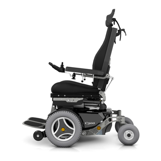
Permobil C300 Service Manual
Power wheelchair
Hide thumbs
Also See for C300:
- Owner's manual (104 pages) ,
- Assembly instruction manual (26 pages) ,
- Service manual (68 pages)
Table of Contents
Advertisement
Advertisement
Table of Contents

Related Manuals for Permobil C300


Summary of Contents for Permobil C300
- Page 1 SERVICE MANUAL Permobil C300 Power wheelchair...
- Page 3 Head Office of the Permobil group Permobil AB Box 120, 861 23 Timrå, Sweden Tel: +46 60 59 59 00. Fax: +46 60 57 52 50 E-mail: info@permobil.se Produced and published by Permobil AB, Sweden Edition no.3, 2009-06 Order no.: 205206-UK-0...
-
Page 4: Table Of Contents
Contents Contents Introduction ....................... 5 Identification plates ..................6 Covers........................ 8 Batteries......................10 Front wheels....................12 Rear wheels..................... 13 Support wheels ....................14 Support wheels dampers ................14 Wheel forks ..................... 15 Shock absorbers..................... 16 Slewing brackets .................... 17 Wheel lock release ..................18 Plastic rail .................... -
Page 5: Introduction
Always state the chassis number when contacting Permobil to ensure that the correct information is provided. Technical Support In the event of technical problems, you should contact your dealer, or Permobil BV Holland at +31-492 554 010. Spare parts Spare parts must be ordered through your dealer. -
Page 6: Identification Plates
Identification plates Identification plates Chassis Chassis identification number. Pilot+ controller Pilot+ controller identification number. Control panel Pilot+ Control panel Pilot+ identification number. - Page 7 Identification plates Control panel VSI Control panel VSI identification number.
-
Page 8: Covers
Covers Covers Removing the Chassis Cover The cover is mounted with hook and loop fastener at the rear and with two knobs at the front. See figure. 1. Move/fold the leg rests out and, if necessary, raise the seat. 2. Switch off the main power switch on the control panel. - Page 9 Covers Removing the Front Battery Cover The cover is wedged in under the chassis cover. 1. Move/fold the leg rests out. 2. Switch off the main power switch on the control panel. 3. If the chassis cover has not been removed, remove the two knobs that hold it in place at the front.
-
Page 10: Batteries
Batteries Batteries WARNING Be careful when using metal objects when working with batteries. A short-circuit can easily cause an explosion. Always use safety gloves and safety goggles. Removing the Front Battery 1. Place the wheelchair on a level surface. 2. Move/fold the leg rests out, and if possible, raise the seat lift 3. - Page 11 Batteries Removing the Rear Battery 1. Place the wheelchair on a level surface. 2. Switch off the main power switch on the control panel. 3. Remove the rear battery cover. See page 9. Battery connections. 4. Disconnect the battery connections. See also the sticker on the battery cover.
-
Page 12: Front Wheels
Front wheels Front wheels Removal 1. Turn off the main power switch on the control panel. 2. Lift the wheelchair chassis and support it on blocks so that the wheel is off the ground. 3. Remove the hubcap (1), bolt (2) and the three washers (3 and 4);... -
Page 13: Rear Wheels
Rear Wheels Rear Wheels Removal 1. Switch off the main power switch on the control panel. 2. Lift up and chock up the wheelchair chassis so that the wheel to be removed is free of the ground. 3. Remove the hub cap 1. 4. -
Page 14: Support Wheels
Support Wheels & Support Wheel Dampers Support Wheels Support wheels may be fitted in three different positions; low, medium and high. These fitting positions are marked L, M and H. With the support wheels fitted in the lower position, low, the wheelchair inclines less before the support wheels meet the ground, but the accessibility of the wheelchair is reduced somewhat. -
Page 15: Wheel Forks
Wheel Forks Wheel Forks Removal 1. Switch off the main power switch on the control panel. 2. Lift up and chock up the wheelchair chassis so that the wheel in question is free of the ground. 3. Remove the cap from the top of the link arm. See figure. -
Page 16: Shock Absorbers
Shock Absorbers Shock Absorbers The shock absorbers may be fitted in two different positions, a standard position(suitable for all users) and a position that produces slightly softer suspension(recommended for user’s with a body weight of 150 lbs or less). Removal 1. -
Page 17: Slewing Brackets
Slewing brackets Slewing brackets Removal 1. Raise the seat; seat elevator to the highest position; fixed seat tube to the service position. See page 24. If the seat elevator does not work normally because the batteries are discharged or the actuator is defective, the seat raised/lowered manually. -
Page 18: Wheel Lock Release
Wheel Lock Release Wheel Lock Release The wheel lock release consists of a plastic rail, a wheel lock release sensor and a magnetic wheel lock on each drive motor. Removing the Plastic Rail 1. Raise the seat; seat elevator to the highest position;... -
Page 19: Magnetic Wheel Lock
Wheel Lock Release Removing the Magnetic wheel lock. 1. Raise the seat; seat elevator to the highest position; fixed seat tube to the service position. See page 24. If the seat elevator does not work normally because the batteries are discharged or the actuator is defective, the seat raised/lowered... -
Page 20: Wheel Lock Release Sensor
Wheel Lock Release Removing the wheel lock release sensor. 1. Raise the seat; seat elevator to the highest position; fixed seat tube to the service position. See page 24. If the seat elevator does not work normally because the batteries are discharged or the actuator is defective, the seat raised/lowered... -
Page 21: Drive Motor
Drive Motor Drive Motor Removal 1. Raise the seat; seat elevator to the highest position; fixed seat tube to the service position. See page 24. If the seat elevator does not work normally because the batteries are discharged or the actuator is defective, the seat raised/lowered manually. -
Page 22: Seat Elevator
Seat elevator Seat elevator Manual Raising/Lowering of the Seat elevator (Applies to Corpus II and PS seats) If the seat lift does not work normally because the batteries are discharged or the actuator is defective, the seat can be raised/lowered manually. -
Page 23: Removing The Seat Elevator
Seat elevator Removing the Seat Elevator 1. Raise the seat to the highest position manually. See the previous page. 2. Switch off the main power switch on the control panel. 3. Remove the chassis cover. See page 8. 4. Remove the seat. NOTE The seat is heavy. -
Page 24: Fixed Seat Post
Fixed seat Post Fixed seat post Service Position The fixed seat post has a service position that facilitates the adjustment of the fixed seat height and other service on the wheelchair. 1. Loosen the screw that locks the fixed height position of the seat post. -
Page 25: Removal
Fixed Seat Post 3. Carefully lift the seat while pressing the service position lock in. Lower the seat to the set height. WARNING Before pressing the service position lock in, lift up and hold the seat in a steady grip, if not, the seat will fall down witch can cause personal injury 4. -
Page 26: Seat Tilt
Innehåll Seat tilt Seat tilt Removal 1. Raise the seat; seat elevator to the highest position; fixed seat tube to the service position. See page 24. If the seat elevator does not work normally because the batteries are discharged or the actuator is defective, the seat raised/lowered manually. -
Page 27: Cs-Seat
CS-seat CS-seat Removal 1. Raise the seat; seat elevator to the highest position; fixed seat tube to the service position. See page 24. If the seat elevator does not work normally because the batteries are discharged or the actuator is defective, the seat raised/lowered manually. -
Page 28: Corpus-Seat
Corpus-seat Corpus-seat Removal 1. Raise the seat; seat elevator to the highest position; fixed seat tube to the service position. See page 24. If the seat elevator does not work normally because the batteries are discharged or the actuator is defective, the seat raised/lowered manually. - Page 29 Corpus-seat Removing seat only on chassis with seat tilt 6. Remove the seat tilt crush protection, it´s fitted with two screws on each side, see figure. 7. Switch on the main power switch on the control panel. Tilt the seat approx. 20°. Switch off the main power switch on the control panel.
-
Page 30: Control Panel Pilot
Control panel Pilot+ & Seat control panel Control panel Pilot+ Removal Switch off the main power switch on the control panel. Disconnect the control panel cable by pulling the connector at the rear of the control panel straight backwards. To remove the control panel, remove the screws holding the common bracket for the control panel and Seat control panel, see figure. -
Page 31: Control Panel Vsi
Control panel VSI Control panel VSI The VSI control panel is a unit that, in addition to a joystick and control buttons, also contains all other electronics required, including a controller. The control panel and complete cabling are replaced as one unit. Removal 1. -
Page 32: Pilot+ Controller
Pilot+ controller Pilot+ controller Removal 1. Switch off the main power switch on the control panel. 2. Remove the rear battery cover. See page 8. 3. Disconnect the electrical connections from the controller. Note their positions. See figure. 4. Remove the controller by unscrewing its two A: SLS circuit board mounting screws. -
Page 33: Sls Drive Stage
SLS Drive Stage SLS Drive Stage (Applies only to Pilot+) Removal 1. Raise the seat; seat elevator to the highest position; fixed seat post to the service position. See page 24. If the seat elevator does not work normally because the batteries are discharged or the actuator is defective, the seat raised/lowered... -
Page 34: Fuses
Fuses Fuses Main Fuse The main fuse is located in its holder inside the front battery cover. NOTE If the main fuse blows, there is often a major electrical fault. The cause of the fault should be checked carefully before the fuse is replaced. -
Page 35: Sls Fuse
Fuses Replacing the SLS Fuse (Applies only to Pilot+) The SLS fuse is located in its holder inside the rear battery cover. 1. Switch off the main power switch on the control panel. 2. Remove the rear battery cover. See page 9. 3. -
Page 36: Control System
The control system can also be programmed in order to make adjustments needed for a specific user. Standard parameter files can be downloaded from the Permobil website, www.permobil.com . To get more information about programming the control system, see the PC-programmer’s technical manual (Order.no: 205009-UK-0). -
Page 37: Trouble Shooting
The troubleshooting guide below describes a number of events that can arise when you use your wheelchair, as well as providing suggestions for solutions. Note that this guide does not describe all the possible events that can arise, and you should always get in touch with your service contact or Permobil when you are unsure... - Page 38 Trouble Shooting Guide Error signals - Battery voltage indicator Every time the wheelchair is started up, a check is performed on parts of the wheelchair’s electronics. If any faults have arisen in these parts, this is shown on the control panel’s battery voltage indicator by one or more blinking lights.
- Page 39 Trouble Shooting Guide CAUSE SOLUTION Check the battery and the connections between the High battery voltage battery and the control unit. Green Failure in wheel lock circuit Check the connections to the magnetic wheel lock. Green Check the contacts to the output stage. If the fault Fault in electronics persists, change the output stage.
-
Page 40: Cabling Overview Vsi
Cabling overview... - Page 41 Cabling overview Cabling overview VSI...
-
Page 42: Cabling Overview Pilot
Cabling overview... - Page 43 Cabling overview Cabling overview Pilot+...
-
Page 44: Distribution Chart Vsi
Distribution Chart... - Page 45 Distribution Chart Distribution Chart VSI...
-
Page 46: Distribution Chart Pilot
Distribution Chart... - Page 47 Distribution Chart Distribution Chart Pilot+...
- Page 48 Notes...
-
Page 49: Index
Index Index Batteries ..........10 Magnetic wheel lock ......19 Cabling overview VSI ......40 Pilot+ controller ......31 Cabling overview Pilot+ ....42 Corpus-seat........28 Control panel Pilot+ ......30 Rear wheels ........13 Control panel VSI ......31 Control System ........ - Page 52 Order no: 205206-UK-0...
Need help?
Do you have a question about the C300 and is the answer not in the manual?
Questions and answers