Permobil C500 Owner's Manual
Permobil c500 power wheelchair owner's manual
Hide thumbs
Also See for C500:
- Owner's manual (100 pages) ,
- Service manual (68 pages) ,
- Assembly instruction manual (26 pages)
Table of Contents
Advertisement
Advertisement
Table of Contents

Related Manuals for Permobil C500


Summary of Contents for Permobil C500
- Page 1 OWNER`S MANUAL Permobil C500 Permobil C500 Power Wheelchair...
- Page 3 6961 Eastgate Blvd. Lebanon, TN 37090 Phone: 800-736-0925 Fax: 800-231-3256 Email: info@permobilusa.com Head Office of the Permobil group Permobil AB Box 120, 861 23 Timrå, Sweden Tel: +46 60 59 59 00. Fax: +46 60 57 52 50 E-mail: info@permobil.se...
- Page 4 Permobil C500 Power Wheelchair Produced and published by Permobil AB, Sweden Edition: 5, 2008-08 Order no. 205209-US-0...
-
Page 5: Table Of Contents
Owner´s Manual Permobil C500 Contents Important Information about the Owner’s Manual..............6 Technical Support ........................7 Spare Parts & Accessories ......................7 Scrapping ..........................7 Warranty............................7 Safety Instructions........................8-23 Design and Function ........................24 General - Overview ........................24 Seat ............................25 Driving - Shock absorbers ....................25 Seat Lift - Seat Tilt ........................26... -
Page 6: Important Information About The Owner's Manual
It is also possible to obtain information concerning our products from our home page on the Internet. You can find us at www.permobil.com. All information, pictures, illustrations and specifications are based upon the product information that was available at the time that these operating instruc- tions were printed. -
Page 7: Technical Support
Owner´s Manual Permobil C500 Important Information about this Owner’s Manual TECHNICAL SUPPORT In the event of technical problems, you should contact your dealer or Permobil Inc USA at 1-800-736-0925. Always state the chassis serial number when contacting Permobil to ensure that the correct information is provided. -
Page 8: Safety Instructions
Permobil is not responsible for personal injuries or property damage resulting from any person’s failure to follow the warnings and instructions in this manual. Permobil is not responsible for injuries or damage resulting from failure to exer- cise good judgment. - Page 9 • that all products ordered are included in the delivery, incuding operating instructions and possible other documentation. If you suspect that something is missing, then contact your supplier or Permobil for more information as soon as possible. • that no transport-related or other damages have occurred to the wheelchair and its accessories.
-
Page 10: Safety Instructions
Safety Instructions WARNING Operation Permobil recommends the use of wheelchair lights at all times user is riding near public rights of way. Use extreme caution when driving near unprotected ledges, drop-offs or on elevated surfaces. Unintended movement or excessive speed in these areas can lead to personal injury or property damage. - Page 11 Permobil products. Weight Limitations The maximum user weight for your Permobil is set forth in the specification section of the supplied Owner´s Manual for current seat model. Operation of the wheelchair by users who exceed the maximum allowable user weight can lead to personal injury and property damage, including damage to the wheel- chair, as well as voiding any applicable warranty to the wheelchair.
- Page 12 Owner´s Manual Permobil C500 Safety Instructions Safety Instructions NOTE Operation - Inclines When driving downhill, select the slowest speed and proceed with caution. Driving down an incline in a front wheel drive wheelchair can shift the user’s center of gravity forward. If the wheelchair rolls faster than you would like, stop the wheelchair by releasing the joystick and begin descending again at a slower speed.
- Page 13 Owner´s Manual Permobil C500 Safety Instructions Safety Instructions WARNING Operation - Inclines Do not drive the wheelchair where the sideways gradient is more than indicated in the technical specifications section of the manual. There is a risk of tipping over.
- Page 14 In order to prevent the wheelchair from rolling away, ensure that the wheelchair is on a level and dry surface before releasing the brakes. In order to avoid personal injury do not use your Permobil in freewheel mode without an attendant present. Do not attempt to put the wheelchair in freewheel mode by yourself while seated in it.
- Page 15 Driving in Extreme Climate Conditions Permobil's wheelchairs are designed to withstand most adverse weather con- ditions, however to minimize the risk of being caught in difficult situations you should avoid using the wheelchair outdoors during, for example, severe cold, heavy rain or thick snow.
- Page 16 Owner´s Manual Permobil C500 Safety Instructions Safety Instructions WARNING Driving with Seat Lift/Seat Tilt/Backrest Recline Be careful in making sure that nothing gets stuck between the chassis and the seat when the seat lift/seat tilt is operated. Operating the seat lift,seat tilt/ back- rest recline changes the center of gravity and increases the risk of tipping over.
- Page 17 Safety Instructions WARNING Positioning Belt Permobil positioning belts are designed to position the user only and will not protect you in an accident. You may even receive further injury from the belts. Support Wheels If your wheelchair is equipped with support wheels, they must always be mounted when the wheelchair is being driven.
- Page 18 Owner´s Manual Permobil C500 Safety Instructions Safety Instructions WARNING Passengers The wheelchair is not intended to transport passengers, regardless of the age of the passenger. The Maximum User Weight stated in the Owner's Manual for your seating includes the user and any personal effects. The Maximum limit should not be exceeded.
- Page 19 Use Prohibited in Motor Vehicles Permobil recommends that users NOT be transported in any kind of vehicle while in their wheelchair, unless the user is in an approved Permobil wheelchair configuration, has secured the wheelchair using a Permolock C, and is using a seatbelt attached to the vehicle.
- Page 20 Failure to do so can lead to personal injury. Do not use parts or accessories not authorized by Permobil. Use of unap- proved ”aftermarket” accessories and parts may cause changes in the wheel- chair, which may make the wheelchair unstable or uncontrollable.
- Page 21 Safety Instructions WARNING Safety Circuits Permobil products are equipped with safety circuits. Inhibit circuits prevent the wheelchair from driving under certain conditions. Speed reduction circuits limit the wheelchair’s maximum speed under certain conditions. Limit switch circuits limit the wheelchair’s functions under certain circumstances. Overload protec- tion circuits shut the wheelchair off in case of an overload.
- Page 22 Permobil and tighten the bolt to the recommended torque. Also, inspect the drive axle and wheel rim for any damage. Damage to either part can cause the wheel bolt to loosen or fracture. Permobil recommends that wheel bolts be used only one time.
-
Page 23: Safety Instructions
The limit values for Electromagnetic Compatibility (EMC) with respect to elec- trical wheelchairs is set in the harmonized standards for the EU in the Medical Devices Directive, No. 93/42/EEC. Permobil's electronic wheelchair’s comply with these limit values. Also see Important Information about Electromagnetic Interference (EMI) on page 94-95. -
Page 24: Design And Function
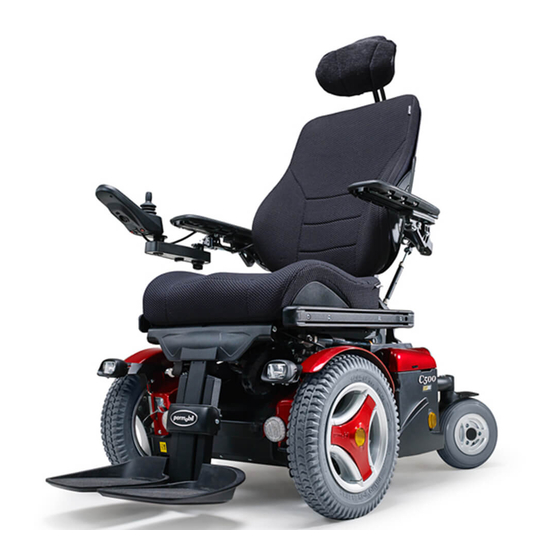
Design and Function Design and Function General The Permobil C500 is a power wheelchair for outdoor and indoor driving intended for persons with functional impairments. The wheelchair consists of a chassis and a seat. The seat consists of the seat frame, seat plate/backrest, armrest/legrest, seat lift/fixed seat and possible accessories and additional options such as a headrest, calf rest, chest support, etc. -
Page 25: Seat
Owner´s Manual Permobil C500 Design and Function Seat The Permobil C500 can be combined with different seat models, which are sup- plied with separate operating instructions. Driving The wheelchair has a drive pack for each drive wheel. The motors regulate the speed, turning and braking. -
Page 26: Seat Lift Seat Tilt
Seat Tilt The Permobil C500 can be fitted with an electric seat tilt actuator adjuster, which lets you adjust the angle of the seat. The electric seat tilt actuator is controlled from the control panel or from the seat control panel. -
Page 27: Wheels
Owner´s Manual Permobil C500 Design and Function Wheels The front wheels have pneumatic tires and the rear wheels can have either pneumatic or solid rubber tires. Lights and Reflectors In the standard version the wheelchair is equipped with reflectors in the front and back as well as on the sides. -
Page 28: Electrical System - Batteries
Electrical system Circuit Breaker Permobil C500 is equipped with a 63A (C500) or 80A (C500s) automatic Circuit Breaker, which can be reset after having been triggered. It also functions as a battery isolator and is controlled (ON/OFF) via the lever located above the left battery cover. - Page 29 Owner´s Manual Permobil C500 Design and Function Electrical System Battteries The wheelchair's two batteries are located under the rear end of the chassis cover. Both of the batteries are easily accessible for maintenance and battery replacement. Location of the Batteries...
-
Page 30: Control Panel Pilot+ - Design And Function
Owner´s Manual Permobil C500 Design and Function Control Panel Pilot+ The Control Panel consists of a joystick, function buttons and indicator lights. Your wheelchair may also be equipped with an extra Seat Control Panel in addition to the control panel. - Page 31 Owner´s Manual Permobil C500 Design and Function Function Buttons/Indicator Lights On the control panel there are a total of 7 function buttons and a total of 3 indi- cator lights. Function Buttons Power Switch, on/off Warning Light Left Turn Indicator ”MODE”...
-
Page 32: Control Panel - Functions
Owner´s Manual Permobil C500 Design and Function Panel Display for Control Panel JSM-L 7key Pilot+ NOTE! If your wheelchair is not equipped with lights (option) the push buttons for lights and turning indicators have no function. However the turning display lamps on the control panel flash when the warning button is activated. - Page 33 Owner´s Manual Permobil C500 Design and Function Lights (option) Warning Horn Press the switch to turn on the lights Press the button to sound the horn of the wheelchair. and attract attention. Speed Display Seat Function Indicator Indicates the adjusted speed at which Indicates active seat function when the wheelchair is set.
-
Page 34: Locking/Unlocking The Wheelchair
Owner´s Manual Permobil C500 Design and Function Locking/Unlocking the Wheelchair Wheelchairs with Pilot+ control system are equipped with a security key which can be used to lock the wheelchair to prevent unauthorized use. To lock the wheelchair: Make sure the wheelchair is switched On. The key should then be inserted into and withdrawn from the panel outlet. - Page 35 Owner´s Manual Permobil C500 Design and Function Joystick The primary function of the joystick is to control the speed and direction of the wheelchair. The further you push the joystick from the center position, the faster the wheelchair will move. When you release the joystick the brakes are auto- matically applied.
-
Page 36: Seat Control Panel
Owner´s Manual Permobil C500 Design and Function Seat Control Panel With this panel, the wheelchair’s electrical seat functions are controlled. NOTE! The number of available functions and their position on the panel, can vary depending on how your wheelchair is equipped. -
Page 37: Leverman - Functions
Owner´s Manual Permobil C500 Design and Function Leverman (Joystick Manager) With the help of Leverman, you can set the maximum speed of the wheelchair and also control the electric seat functions. Speed Selector Press MODE button once. The speed indicator lights flash and by moving the joystick to the right/left you can increase/decrease the maximum speed of the wheelchair. -
Page 38: Control Panel R-Net - Design And Function
Owner´s Manual Permobil C500 Design and Function Control Panel R-Net The Control Panel consists of a joystick, function buttons and an LCD Screen. At the back of the panel you also find the Charger Socket and two Jack Sockets. Your wheelchair may also be equipped with an extra Seat Control Panel in addition to the control panel. -
Page 39: Charger Socket
Owner´s Manual Permobil C500 Design and Function Charger Socket This socket should only be used for charging or locking the wheelchair. Do not connect any type of programming cable into this socket This socket should not be used as a power supply for any other electrical device. Connection of other electrical devices may damage the control system or affect the E.M.C. -
Page 40: Locking - Unlocking The Wheelchair
Owner´s Manual Permobil C500 Design and Function Locking the Control System The Control System can be locked in one of two ways. Either using a button sequence on the keypad or with a physical Key. How the Control system is locked depends on how your system is programmed. - Page 41 Owner´s Manual Permobil C500 Design and Function Key Locking To lock the wheelchair with a key lock: • Insert and remove a PGDT supplied key into the Charger Socket on the Joystick Module. • The wheelchair is now locked. The following screen will be displayed.
-
Page 42: Function Buttons
Owner´s Manual Permobil C500 Design and Function Function Buttons On the control panel there are a total of 10 Function Buttons. Horn Button On/Off Button Speed Buttons PROFILE MODE Decrease / Increase Profile Button Mode Button Lights Button & LED Hazard Button &... - Page 43 Owner´s Manual Permobil C500 Design and Function Speed Increase Button This button increases the maximum speed setting. Depending on the way the control system has been programmed a momentary screen may be displayed when the button is pressed. Mode Button The Mode button allows the user to navigate through the available operating Modes for the control system.
-
Page 44: Jack Sockets
Owner´s Manual Permobil C500 Design and Function Jack Sockets External On/Off Switch Jack This allows the user to turn the control system on and off using an external device, such as a buddy button. External Profile Switch Jack (If profiles programmed/used) This allows the user to select Profiles using an external device, such as a buddy button. -
Page 45: Lcd Screen
Owner´s Manual Permobil C500 Design and Function LCD Screen The status of the control system can be understood by observing the LCD screen. The control system is on when the screen is backlit. Screen Symbols The Drive screen for the R-net has common components, wich will always appear, and components wich will only appear under certain conditions. - Page 46 Owner´s Manual Permobil C500 Design and Function Speed Indicator This displays the current speed setting. The speed setting is adjusted using the Speed Buttons. Current Profile The Profile Number describes wich Profile the con- trol system is currently operating in. The Profile Text is the name or description of the Profile the control system is currently operating in.
- Page 47 Owner´s Manual Permobil C500 Design and Function Fault The control system can detect a wide variety of errors. When the system has detected an error that is not severe enough to cause the system to trip, then this symbol will be displayed.
-
Page 48: Handling
Owner´s Manual Permobil C500 Handling Handling General The Wheelchair is designed for indoor and outdoor use. When driving indoors, you must observe care when driving in, for example, narrow passageways, when pass- ing through doors and entries as well as when using elevators, ramps, etc. Also be... -
Page 49: Driving Technique
Always bear in mind that a high speed and extended braking distance entail an increased risk of accidents. We recommend the use of a positioning seat belt when driving the Permobil C500. In the event of the wheelchair moving in an unexpected way, RELEASE THE JOYSTICK! -
Page 50: Driving Rules
Owner´s Manual Permobil C500 Handling Driving Rules Support Wheels Your wheelchair can be equipped with support wheels mounted at the front to minimize the risk of the wheelchair tipping over forward when passing obstacles and the like. If your wheelchair is equipped with support wheels, they must always be mounted when the wheelchair is being driven. - Page 51 Owner´s Manual Permobil C500 Handling Driving over Obstacles Do not drive the wheelchair over obstacles of a height greater than 3 inches. Driving over tall edges increases the risk of tipping over as well as the risk of damage to the wheelchair.
- Page 52 Owner´s Manual Permobil C500 Handling Driving on Downhill Slopes Driving on downhill slopes must always be done at a low speed and with great care. Avoid rapid braking, abrupt avoidance maneuvers and never maintain a speed higher than that at which you can maneuver the wheelchair in a safe and secure manner.
- Page 53 Owner´s Manual Permobil C500 Handling Driving on Uphill Slopes Driving on uphill slopes must always be performed with great care. Avoid abrupt avoidance maneuvers and never maintain a speed higher than that at which you can maneuver the wheelchair in a safe and secure manner.
- Page 54 Owner´s Manual Permobil C500 Handling Driving with Sideways Slopes Driving with a sideways slope must always be performed with great care. Avoid abrupt avoidance maneuvers and never maintain a speed higher than that at which you can maneuver the wheelchair in a safe and secure manner.
-
Page 55: Magnetic Wheel Locks
Make sure that the person pushing the wheelchair has full control when wheel locks are disengaged. Always make sure that the wheel locks are engaged after manually moving the wheelchair. NOTE When the wheel locks are released, the chair will not drive. If it does, contact your Permobil serviceman as soon as possible. -
Page 56: Charging The Batteries
Owner´s Manual Permobil C500 Handling Battery Charging The amount of charge in your batteries depends on a number of factors, includ- ing the way you use your wheelchair, the temperature of the batteries, their age and the way they are made. These factors will affect the distance you can trav- el in your wheelchair. - Page 57 Ensure that the charger plug is pushed fully in position. You will not be able to drive the wheelchair when the charger is connected. If the wheelchair does drive with the charger plugged in, contact your Permobil serviceman as soon as possible. WARNING Only use the battery charger that has been supplied with your wheelchair or recommended by Permobil.
-
Page 58: Transport
If your wheelchair is equipped with a Luggage Box (option) difficulty may occur to anchor the wheel- chair at the rear fastening brackets. This can be solved by ordering an extra pair of Rear Fastening Brackets. Please contact Permobil or your nearest dealer for more information and how to order. - Page 59 Never sit in your wheelchair while in a moving vehicle. In an accident or sudden stop you may be thrown from the chair and seriously injured or killed. Permobil positioning belts are designed to position the user only and will not protect you in an acci- dent. You may even receive further injury from the belts.
-
Page 60: Air Transport
Owner´s Manual Permobil C500 Transport General Advice for Air transport Please refer to the Air Carrier Access Act at 49 USC § 41705 and accompanying regulations at 14 CFR Part 382 for specific guidelines and regulations pertaining to transporting wheelchairs on aircraft in the United States. -
Page 61: General Advice For Air Transport
Owner´s Manual Permobil C500 Transport General Advice for Air transport 3. Preventing Damages The electronic components, as well as other critical parts, in your wheelchair are highly sophisticated and fragile and care must be taken to protect them. When transporting your wheelchair by air, we recommend that you cover the control panel with soft, shock-absorbing material (foamed plastic or similar) and fold it in towards the backrest. -
Page 62: Maintenance And Repairs
Owner´s Manual Permobil C500 Maintenance and Repairs Maintenance and Repairs To ensure that your wheelchair works well, you must inspect, maintain, and obtain routine service on it regularly. Every wheelchair is subject to wear and tear between the moving parts and also due to the strains and stresses of typical use. -
Page 63: General Batteries/Storage
Owner´s Manual Permobil C500 Maintenance and Repairs General Batteries/Storage • Note that a battery drains on its own and a discharged battery can freeze and burst when it is cold. If the wheelchair must be stored without being used for a longer period of time, the batteries should always be charged up once per month so that they do not incur any damage. -
Page 64: Finishes Care - Wheels
Owner´s Manual Permobil C500 Maintenance and Repairs Finishes Care and Maintenance With regular care and maintenance, your Permobil will provide years of superior performance and satisfaction. To maintain the finish quality of your wheelchair, please follow the cleaning procedures provided below. - Page 65 Owner´s Manual Permobil C500 Maintenance and Repairs Wheels Check at regular intervals that the wheelchair's tires have the prescribed tire pres- sure. An incorrect tire pressure can cause deterioration in stability and manuever- ability, plus extremely low air pressure can give rise to abnormal wear as well as shorter driving distances.
- Page 66 If the wheel bolt is removed for tire service, replace it with a new, unused part from Permobil and tight- en the bolt to the recommended torque. Also, inspect the drive axle and wheel rim for any damage.
-
Page 67: Wheel Lock Release
Owner´s Manual Permobil C500 Maintenance and Repairs Wheel Lock Release Check regularly, approx. once per month, the functionality of the wheel lock release and lever safety catch. It must not be possible to drive the wheelchair when the wheel locks are disengaged. -
Page 68: Changing The Batteries
Owner´s Manual Permobil C500 Maintenance and Repairs Changing the Batteries (Also see Stickers inside the Battery Covers.) 1. Put the wheelchair on a level surface. 2. Shut off the power supply with the On/Off button on the control panel and put the Circuit Breaker in OFF position. - Page 69 Owner´s Manual Permobil C500 Maintenance and Repairs Changing the Batteries 7. Lift the batteries away by using the battery straps. 8. Use the battery straps and connect new batteries in reverse order (leave the straps on the new batteries). 9. Close and lock the battery covers and reassembly the chassis cover.
-
Page 70: Circuit Breaker And Charging Fuse
Owner´s Manual Permobil C500 Maintenance and Repairs Resetting the Circuit Breaker WARNING A triggered automatic Circuit Breaker can indicate larger electrical faults. The cause should be checked carefully before the Circuit Breaker is reset. Always contact an authorized serviceman or Permobil when in doubt. -
Page 71: Replacement Of Charging Fuse
Owner´s Manual Permobil C500 Maintenance and Repairs Replacement of Charging Fuse, 15A The charging fuse is located under the main chassis cover. To replace the charg- ing fuse, you must remove the main and front center chassis cover. • Remove the small front center chassis cover. The cover is fastened with four plastic plugs, and can be removed by pulling the cover upwards by hand. -
Page 72: Technical Specifications
Technical Specifications Technical Specifications The specifications given in the following pages are only applicable to the Permobil C500 chassis with Corpus II Seat. For size and weight information about each seat, see the Owner’s Manual accompanying the seat. Length 49,5”... -
Page 73: Data - Electric System
Length................49,5” Width................25,5” Height C500 ..............52,5” Height C500 Lowrider ............47,5” Smallest Transport Size, lxwxh C500 ......37,5x25,5x33” Smallest Transport Size, lxwxh C500 Lowrider ....37,5x25,5x32” Weight incl. Batteries and Corpus-Seat ......350 lbs Max. Battery Size ............10,25x6,75x8,25” Wheels Tire Size, front..............300 x 8 Tire Size, back ..............210 x 65 Max Air Pressure, front/back tires ........29 psi (200 kPa) -
Page 74: Troubleshooting Guide
Note that this guide does not describe all the possible events that can arise, and you should always get in touch with your service contact or Permobil when you are unsure. - Page 75 Owner´s Manual Permobil C500 Technical Specifications EVENT POSSIBLE CAUSE SOLUTION The wheelchair can only Seat lift raised from its Lower the seat lift. be driven with reduced speed. lowest position. See pages 26. Applies for electrical seat lift only. The wheelchair will Circuit Breaker set in ”OFF”...
-
Page 76: Error Signals, Electronics Pilot
Owner´s Manual Permobil C500 Troubleshooting Guide Error signals - Battery voltage Indicator (Only applies to Pilot+). Every time the wheelchair is started up, a check is performed on parts of the wheelchair’s elec- tronics. If any faults have arisen in these parts, this is shown on the control panel’s battery volt-... - Page 77 Owner´s Manual Permobil C500 Troubleshooting Guide CAUSE SOLUTION Check the battery and the connections between High battery voltage Green the battery and the control unit. Check the connections to the magnetic wheel Failure in wheel lock circuit Green lock. Check the contacts to the output stage. If the fault...
-
Page 78: R-Net Diagnostics
Diagnostics should only be conducted by healthcare professionals with in-depth knowledge of PGDT electronic control systems. An incorrect or badly effected repair could result in an unsafe set-up of a wheelchair. Permobil accept no liability for losses of any kind arising from an incorrect or badly effected repair. -
Page 79: Diagnostic Screens
Owner´s Manual Permobil C500 R-net Diagnostics Diagnostic Screens Current Diagnostic Screen When the control system safety circuits have operated and the control system has been prevented from moving the wheelchair a diagnostics screen will be displayed. This indicates a system trip, i.e. the R-net has detected a problem somewhere in the wheelchair’s electrical system. - Page 80 Owner´s Manual Permobil C500 R-net Diagnostics 2.1.4 Example The example screen shown below show the following information: Identified Module: Power Module Trip. Trip Text: Low Battery Trip Code: 2C00 This means the battery needs charging or there is a bad connection to the battery.
- Page 81 The trips are stored in their respective Modules within the system. The System Log is entered using On Board Programming, OBP. For more information about OBP, contact Permobil or your service agent. Enter OBP Mode • Select System from the menu.
-
Page 82: Diagnostic Text Definitions
Owner´s Manual Permobil C500 R-net Diagnostics Diagnostic Text Definitions Once a trip text and module have been established use the following definitions to ascertain the possible cause and required corrective procedure. Trip Text Referral Point Joystick Error Refer to section 3.1 Low Battery Refer to section 3.2... - Page 83 Owner´s Manual Permobil C500 R-net Diagnostics Joystick Error The most common cause of this trip is if the joystick is deflected away from cen- ter before and during the time the control system is switched on. The joystick displaced screen will be displayed for 5 seconds, if the joystick is not released within that time then a trip is registered.
- Page 84 Owner´s Manual Permobil C500 R-net Diagnostics Brake Error This occurs when the control system detects a problem in the solenoid brakes or the connections to them. 1505 - M1 Brake Error. 1506 - M2 Brake Error. • Check the solenoid brakes, cables and connections to the control system.
- Page 85 Owner´s Manual Permobil C500 R-net Diagnostics Joystick Calibration Error This occurs when the Joystick Calibration process has not been successful. • Enter OBP and attempt calibration. If the trip is still present after the above has been attempted, then the Joystick Module may be defective.
- Page 86 Owner´s Manual Permobil C500 R-net Diagnostics 3.11 Indicator Lamp Short This occurs when the control system detects a short in either of the Indicator Circuits. 7206 - Left Indicator Short. 720A - Right Indicator Short. • Check the indicators, cables and connections to the control system.
- Page 87 PGDT control systems. Incorrect programming could result in an unsafe set-up of a wheelchair for a user. Permobil accept no responsibility for losses of any kind if the programming of the control system is altered from the factory pre-set values.
- Page 88 Owner´s Manual Permobil C500 R-net Diagnostics 3.19 Bad Cable This occurs when the control system detects a fault in the wiring in the communi- cation cables between any of the modules. • Check all cables and connections for continuity. • If there is any visible damage to cables, replace and cycle power.
- Page 89 Owner´s Manual Permobil C500 R-net Diagnostics 3.22 System Error This occurs when the system detects a trip which cannot be attributed to a specific module. • Check all cables and connections. • Cycle the power. If the trip is still present and the system contains 3rd party Modules: •...
- Page 90 WARNING These tests should be conducted in an open space and a restraining device such as a seat belt should always be used. Permobil accepts no liability for losses of any kind arising from failure to comply with this condition.
- Page 91 Owner´s Manual Permobil C500 R-net Diagnostics Brake Test These tests should be carried out on a level floor with at least one meter clear space around the wheelchair. • Switch on the control system. • Check that the screen remains on after initialisation.
- Page 92 Owner´s Manual Permobil C500 R-net Diagnostics Lights, Indicators and Hazard Lamps Test If lights are fitted: • Visually check each bulb for correct illumination. • Check each bulb for correct illumination and that the flashrate is 1.5Hz ± 0.5Hz. • Disconnect each bulb in turn and check that the remaining bulb for that side flashes at 3Hz ±...
- Page 93 Any replacement work carried out without Permobils permission will invalidate the control system’s warranty. NOTE Permobil accept no liability for losses of any kind arising from unauthorized opening, adjustments or modifications to a any component of the R-net control system.
-
Page 94: Important Information About Electromagnetic Interference (Emi)
Owner´s Manual Permobil C500 Electromagnetic Interference WARNING It is very important that you read this information regarding the possible effects of Electromagnetic Interference on your powered wheelchair. Electromagnetic Interference (EMI) From Radio Wave Sources Powered wheelchairs and motorized scooters (in this text, both will be referred... - Page 95 Owner´s Manual Permobil C500 Electromagnetic Interference NOTE! Other types of hand-held devices, such as cordless phones, laptop com- puters, AM/FM radios, TV sets, CD players, and casette players, and small appli- ances, such as electric shavers and hair dryers, so far we know, are not likely to cause EMI problems to your powered wheelchair.
-
Page 96: Accessories
Owner´s Manual Permobil C500 Accessories Accessories We are constantly developing accessories for our wheelchairs. Contact your nearest Permobil retailer for more information about the accessories available for your wheelchair. - Page 97 Owner´s Manual Permobil C500 Notes...
- Page 100 Permobil C500 Order no: 205209-US-0 Order no: 205209-US-0...
Need help?
Do you have a question about the C500 and is the answer not in the manual?
Questions and answers