
Related Manuals for Daikin SkyAir Super Inverter 70 D Series


Summary of Contents for Daikin SkyAir Super Inverter 70 D Series
- Page 1 SiE25-110 Service Manual Split System Air Conditioners SkyAir R-407C Super Inverter 70 D Series [Applied Models] SkyAir : Inverter Heat Pump...
-
Page 2: Table Of Contents
SkyAir Super Inverter 70 D Series 1. Introduction .................... V 1.1 Safety Cautions ..................v SkyAir Super Inverter 70 D Series Heat Pump ......1 Part1 Model Name and Power Supply .........3 1. Model Name and Power Supply..............4 1.1 Model Name and Power Supply .............. 4 1.2 External Appearance ................ - Page 3 SiE25-110 Part 6 Field Setting ..............39 1. Method of Field Set (Reset after Maintenance Inspection/Repair) ..40 1.1 Explanation.................... 40 1.2 Field Setting................... 41 1.3 Initial Setting Contents................43 1.4 Local Setting Mode No................44 1.5 Detailed Explanation of Setting Modes..........46 1.6 Centralized Group No.
- Page 4 SiE25-110 3.11 Remote Controller LCD Displays "88"..........119 3.12 Swing Flap does not Operate .............. 120 4. Procedure of Self-Diagnosis by Remote Controller ......121 4.1 The INSPECTION/TEST Button............121 4.2 Self-Diagnosis by Wired Remote Controller ........122 4.3 Fault Diagnosis by Wireless Remote Controller ........123 4.4 Remote Controller Display Malfunction Code and Contents ....
- Page 5 SiE25-110 6.39 Transmission Error Between Main Remote Controller and Sub Remote Controller ..............184 6.40 Malfunction of Field Setting Switch............185 6.41 Centralized Address Setting Error ............187 Part 9 Removal Procedure ............195 1. FHYCP71~140D .................196 1.1 Removal of Suction Grille ..............196 1.2 Removal of Air Filter ................
-
Page 6: Introduction
SiE25-110 Introduction 1. Introduction Safety Cautions Cautions and Be sure to read the following safety cautions before conducting repair work. The caution items are classified into “ Warning ” and “ Caution ”. The “ Warning ” Warnings items are especially important since they can lead to death or serious injury if they are not followed closely. -
Page 7: Cautions Regarding Products After Repair
Introduction SiE25-110 Caution Do not repair the electrical components with wet hands. Working on the equipment with wet hands can cause an electrical shock. Do not clean the air conditioner by splashing water. Washing the unit with water can cause an electrical shock. Be sure to provide the grounding when repairing the equipment in a humid or wet place, to avoid electrical shocks. -
Page 8: Inspection After Repair
SiE25-110 Introduction Warning Be sure to use the specified cable to connect between the indoor and outdoor units. Make the connections securely and route the cable properly so that there is no force pulling the cable at the connection terminals. Improper connections can cause excessive heat generation or fire. -
Page 9: Using Icons
Introduction SiE25-110 Caution Check to see if the parts and wires are mounted and connected properly, and if the connections at the soldered or crimped terminals are secure. Improper installation and connections can cause excessive heat generation, fire or an electrical shock. If the installation platform or frame has corroded, replace it. -
Page 10: Skyair Super Inverter 70 D Series Heat Pump
SiE25-110 SkyAir Super Inverter 70 D Series Heat Pump Model Series Class Pair 100D 125D 140D FHYCP Twin — 50D×2 60D×2 — Pair 100B 125B — Indoor Units FHYP Twin — 45B×2 60B×2 — FUYP 100B 125B — FAYP 100B —... - Page 11 SiE25-110...
-
Page 12: Part1 Model Name And Power Supply
SiE25-110 Part 1 Model Name and Power Supply 1. Model Name and Power Supply..............4 1.1 Model Name and Power Supply .............. 4 1.2 External Appearance ................5 Model Name and Power Supply... -
Page 13: Model Name And Power Supply
Model Name and Power Supply SiE25-110 1. Model Name and Power Supply Model Name and Power Supply 50Hz Model Series Indoor Units Outdoor Units Power Supply FHYCP71DVE RZP71DV1 FHYCP100DVE Ceiling RZP100DV1 Mounted FHYCP50DVE+FHYCP50DVE (Twin) Cassette Type FHYCP125DVE RZP125DV1 FHYCP60DVE+FHYCP60DVE (Twin) FHYP71BV1 RZP71DV1 FHYP100BV1... -
Page 14: External Appearance
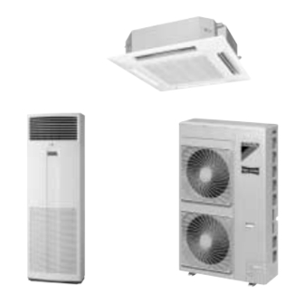
SiE25-110 Model Name and Power Supply External Appearance Indoor Units FHYP-B FHYCP-D FAYP-B FUYP-B Remote Controller Wired Type Wireless Type Outdoor Units RZP71D RZP100D RZP125D RZP140D Model Name and Power Supply... - Page 15 Model Name and Power Supply SiE25-110 Model Name and Power Supply...
-
Page 16: Part 2 Functions
SiE25-110 Part 2 Functions 1. List of Functions ..................8 1.1 Functions ....................8 Functions... -
Page 17: List Of Functions
List of Functions SiE25-110 1. List of Functions Functions FHYCP / FUYP New Ceiling Ceiling Mounted Mounted Super Cassette Suspended Items Improved Points and Functions (FHYCP) Cassette (FUYP) 50~140D 71~125B Indoor Units Model Type Outdoor Units Appearance Improved Main Reduction of Dimensions or Weight Improvement Reduction of Operation Sound Auto Restart... - Page 18 SiE25-110 List of Functions FHYP/FAYP Ceiling Suspended Wall Mounted (FHYP) (FAYP) Items Improved Points and Functions 50~125B 71, 100B Indoor Units Model Type Outdoor Units Appearance Improved Main Reduction of Dimensions or Improvement Weight Reduction of Operation Sound Auto Restart Fan Operation Mode LCD Remote Controller (Option) Auto Swing Function...
- Page 19 List of Functions SiE25-110 Items Functions RZP71~140D Inverter Control Comfortable PMV Control Conditioning MIO Control Cooling –5~50˚CDB Operation Wide Operation Range Range Heating –15~15.5˚CWB Note: PMV : Predicted Mean Vote MIO : Multi Input and Output Functions...
-
Page 20: Part 3 Specifications
SiE25-110 Part 3 Specifications 1. Specifications ..................12 1.1 50Hz ...................... 12 1.2 60Hz ...................... 18 1.3 Comply with Australian Standard (50Hz)..........20 Specifications... -
Page 21: Specifications
Specifications SiE25-110 1. Specifications 50Hz FHYCP (Ceiling Mounted Cassette Type: Pair System) Indoor Units FHYCP71DVE FHYCP100DVE FHYCP125DVE Model Outdoor Units RZP71DV1 RZP100DV1 RZP125DV1 7.1 (3.3~8.0) 10.0 (5.0~11.4) 12.5 (6.0~14.3) 1 Cooling Capacity (1) Btu/h 24,200 (11,200~27,300) 34,100 (17,000~38,900) 42,600 (20,400~48,800) (Min~Max) kcal/h 6,100 (2,800~6,800) - Page 22 SiE25-110 Specifications FHYCP (Ceiling Mounted Cassette Type: Twin Stem) Indoor Units FHYCP50DVE×2 FHYCP60DVE×2 Model Outdoor Units RZP100DV1 RZP125DV1 10.0 (5.0~11.4) 12.5 (6.0~14.3) 1 Cooling Capacity (1) Btu/h 34,100 (17,000~38,900) 42,600 (20,400~48,800) (Min.~Max.) kcal/h 8,600 (4,300~9,800) 10,700 (5,100~12,200) 11.2 (5.6~12.8) 14.0 (6.0~16.2) 1 Heating capacity Btu/h 38,200 (19,100~43,600)
- Page 23 Specifications SiE25-110 FHYP (Ceiling Suspended Type: Pair System) Indoor Units FHYP71BV1 FHYP100BV1 FHYP125BV1 Model Outdoor Units RZP71DV1 RZP100DV1 RZP125DV1 7.1 (3.3~8.0) 10.0 (5.0~11.4) 12.5 (6.0~14.3) 1 Cooling Capacity Btu/h 24,200 (11,200~27,300) 34,100 (17,000~38,900) 42,600 (20,400~48,800) kcal/h 6,100 (2,800~6,800) 8,600 (4,300~9,800) 10,700 (5,100~12,200) 8.0 (3.5~9.0) 11.2 (5.6~12.8)
- Page 24 SiE25-110 Specifications FHYP (Ceiling Suspended Type: Twin System) Indoor Units FHYP45BV1×2 FHYP60BV1×2 Model Outdoor Units RZP100DV1 RZP125DV1 10.0 (5.0~11.4) 12.5 (6.0~14.3) 1 Cooling Capacity Btu/h 34,100 (17,000~38,900) 42,600 (20,400~48,800) kcal/h 8,600 (4,300~9,800) 10,700 (5,100~12,200) 11.2 (5.6~12.8) 14.0 (6.0~16.2) 1 Heating Capacity Btu/h 38,200 (19,100~43,600) 47,700 (20,400~55,300)
- Page 25 Specifications SiE25-110 FUYP (New Ceiling Suspended Cassette Type) Indoor Units FUYP71BV1 FUYP100BV1 FUYP125BV1 Model Outdoor Units RZP71DV1 RZP100DV1 RZP125DV1 7.1 (3.3~8.0) 10.0 (5.0~11.4) 12.5 (6.0~14.3) 1 Cooling Capacity Btu/h 24,200 (11,200~27,300) 34,100 (17,000~38,900) 42,600 (20,400~48,800) kcal/h 6,100 (2,800~6,800) 8,600 (4,300~9,800) 10,700 (5,100~12,200) 8.0 (3.5~9.0) 11.2 (5.6~12.8)
- Page 26 SiE25-110 Specifications FAYP (Wall Mounted Type) Indoor Units FAYP71BV1 FAYP100BV1 Model Outdoor Units RZP71DV1 RZP100DV1 7.1 (3.3~8.0) 10.0 (5.0~11.4) 1 Cooling Capacity Btu/h 24,200 (11,200~27,300) 34,100 (17,000~38,900) kcal/h 6,100 (2,800~6,800) 8,600 (4,300~9,800) 8.0 (3.5~9.0) 11.2 (5.6~12.8) 1 Heating Capacity Btu/h 27,300 (11,900~30,700) 38,200 (19,100~43,600) kcal/h...
-
Page 27: 60Hz
Specifications SiE25-110 60Hz FHYCP (Ceiling Mounted Cassette Type) Indoor Units FHYCP71DVL FHYCP100DVL Model Outdoor Units RZP71DVAL RZP100DVAL 7.1 / 7.2 10.0 / 10.1 (3.3~8.1) / (3.4~8.2) (5.0~11.4) / (5.1~11.6) 24,200 / 24,500 34,100 / 34,400 1 Cooling Capacity (1)/(2) Btu/h (11,200~27,600) / (11,600~27,900) (17,000~38,900) / (17,400~39,600) 6,100 / 6,100... - Page 28 SiE25-110 Specifications FHYCP (Ceiling Mounted Cassette Type) Indoor Units FHYCP125DVL FHYCP140DVL Model Outdoor Units RZP125DTAL RZP140DTAL 12.5 / 12.7 14.0 / 14.2 (6.0~14.3) / (6.1~14.5) (6.2~15.8) / (6.3~16.1) 42,600 / 43,300 47,700 / 48,400 1 Cooling Capacity (1)/(2) Btu/h (20,400~48,800) / (20,800~49,500) (21,100~53,900) / (21,500~54,900) 10,700 / 10,900 12,000 / 12,200...
-
Page 29: Comply With Australian Standard (50Hz)
Specifications SiE25-110 Comply with Australian Standard (50Hz) FHYCP (Ceiling Mounted Cassette Type: Pair System) Indoor Units FHYCP71DVE FHYCP100DVE FHYCP125DVE Model Outdoor Units RZP71DV1 RZP100DV1 RZP125DV1 6.9 (3.2~7.8) 9.7 (4.9~11.0) 12.1 (5.8~13.8) 1 Cooling Capacity Btu/h 23,500 (10,900~26,600) 33,100 (16,700~37,500) 41,300 (19,800~47,100) (Min.~Max.) kcal/h 5,900 (2,700~6,700) - Page 30 SiE25-110 Specifications FHYCP (Ceiling Mounted Cassette Type: Twin System) Indoor Units FHYCP50DVE×2 FHYCP60DVE×2 Model Outdoor Units RZP100DV1 RZP125DV1 9.7 (4.9~11.0) 12.1 (5.8~13.8) 1 Cooling Capacity Btu/h 33,100 (16,700~37,500) 41,300 (19,800~47,100) (Min.~Max.) kcal/h 8,300 (4,200~9,400) 10,400 (4,900~11,800) 11.0 (5.5~12.6) 13.7 (5.9~15.9) 1 Heating Capacity Btu/h 37,500 (18,700~43,000)
- Page 31 Specifications SiE25-110 Specifications...
-
Page 32: Part 4 Remote Controller
SiE25-110 Part 4 Remote Controller 1. Wired Remote Controller...............24 1.1 Wired Remote Controller - NEW MODEL (For Cooling only and heat-pump Model) ..........24 1.2 Installation ..................... 26 2. Wireless Remote Controller ..............28 2.1 Wireless Remote Controller..............28 Remote Controller... -
Page 33: Wired Remote Controller
Wired Remote Controller SiE25-110 1. Wired Remote Controller Wired Remote Controller - NEW MODEL (For Cooling only and heat-pump Model) BRC1C61 FHYCP, FHYP, FUYP, FAYP BRC1C61 BRC1C61 BRC1B61 ON / OFF Operation with Air Conditioner Independent operation in intermediate season Ventilation mode change over (Auto / HRV / Normal) Air flow change over... - Page 34 SiE25-110 Wired Remote Controller TIMER MODE START/STOP BUTTON ON/OFF BUTTON Press the button and the system will start. Press the button again and the system will TIMER ON/OFF BUTTON stop. OPERATION LAMP (RED) INSPECTION/TEST OPERATION BUTTON The lamp lights up during operation. This button is used only by qualified service DISPLAY “...
-
Page 35: Installation
Wired Remote Controller SiE25-110 Installation Remote Controller... - Page 36 SiE25-110 Wired Remote Controller Remote Controller...
-
Page 37: Wireless Remote Controller
Wireless Remote Controller SiE25-110 2. Wireless Remote Controller Wireless Remote Controller Names and Function Model Series Name of Option FHYCP FHYP FUYP FAYP BRC7E61W BRC7E63W BRC7C528W BRC7C610W Remote Controller ON OFF DOWN ON OFF TEMP TIME DOWN RESERVE CANCEL TIMER TEST MODE SWING... - Page 38 SiE25-110 Wireless Remote Controller TIMER RESERVE/CANCEL BUTTON DISPLAY “ ” (SIGNAL TRANSMISSION) This lights up when a signal is being AIR FLOW DIRECTION ADJUST transmitted. BUTTON DISPLAY “ ” “ ” “ ” “ ” OPERATION MODE SELECTOR “ ” (OPERATION MODE) BUTTON This display shows the current OPER- Press this button to select OPERATION...
- Page 39 Wireless Remote Controller SiE25-110 Remote Controller...
-
Page 40: Part 5 Field Piping And Wiring
SiE25-110 Part 5 Field Piping and Wiring 1. Field Piping and Wiring .................32 1.1 Precautions.................... 32 1.2 Field Piping.................... 35 1.3 Field Wiring.................... 37 Field Piping and Wiring... -
Page 41: Field Piping And Wiring
Field Piping and Wiring SiE25-110 1. Field Piping and Wiring Precautions Caution to be Taken When Brazing Refrigerant Piping “Do not use flux when brazing copper-to-copper refrigerant piping. (Particularly for the HFC refrigerant piping) Therefore, use the phosphor copper brazing filler metal (BCuP) which does not require flux.”... - Page 42 SiE25-110 Field Piping and Wiring Procedure and Tools for Refrigerant Piping Work Procedure Piping work for R-407C model partially differs from R-22 model in items and procedures of piping work and refrigerant charging due to different component and higher pressure for R-407C. The below chart shows general work procedure for R-407C model. Determination of work item Confirm the refrigerant is R-407C or R-22 Check the refrigerant to be used...
- Page 43 Field Piping and Wiring SiE25-110 Tools Several dedicated tools are required for the installation work of R-407C models. Some of conventional tools can be used except tools actually used to the installation work for R-22 models. Tool name Work process / Usage Interchangeability with conventional tool Pipe cutter Pipe cutting...
-
Page 44: Field Piping
SiE25-110 Field Piping and Wiring Field Piping This unit requires additional charging of refrigerant according to the length of pipe connected at the site. When the entire refrigerant pipe length is within 30 meters, the additional changing is not needed. Take the following steps for proper charging. - Page 45 Field Piping and Wiring SiE25-110 (4) Precautions for pumping-down operation (When moving and remounting the indoor or outdoor units, etc.) When running pump-down operation, turn off the power and protect the terminal block to prevent it from coming into contact with the insulating sheet, as shown in the figure. Top plate Terminal block Switch box...
-
Page 46: Field Wiring
SiE25-110 Field Piping and Wiring Necessity of a trap Since there is fear of the oil held inside the riser piping flowing back into the compressor when stopped and causing liquid compression phenomenon, or cases of deterioration of oil return, it will be necessary to provide a trap at an appropriate place in the riser gas piping. - Page 47 Field Piping and Wiring SiE25-110 WARNING Electrical wiring must be carried out by qualified personnel. Before obtainging access to terminal devices, all supply circuits munt be interrupted. CAUTION Be sure to ground the air conditioner. Do not connect the earth wire to a gas pipe, water pipe, lightning conductor or telephone earth wire. Use only copper wires.
-
Page 48: Part 6 Field Setting
SiE25-110 Part 6 Field Setting 1. Method of Field Set (Reset after Maintenance Inspection/Repair)........40 1.1 Explanation.................... 40 1.2 Field Setting................... 41 1.3 Initial Setting Contents................43 1.4 Local Setting Mode No................44 1.5 Detailed Explanation of Setting Modes..........46 1.6 Centralized Group No. -
Page 49: Method Of Field Set (Reset After Maintenance Inspection/Repair)
Method of Field Set (Reset after Maintenance Inspection/Repair) SiE25-110 1. Method of Field Set (Reset after Maintenance Inspection/Repair) Explanation Field set is carried out from the remote controller. At time of installation, or after maintenance inspection/repair, carry out field set according to the explanation below. Incorrect settings will cause a malfunction to occur. -
Page 50: Field Setting
SiE25-110 Method of Field Set (Reset after Maintenance Inspection/Repair) Field Setting 1.2.1 Wired Remote Controller Notes: (Field setting must be made from the remote controller in accordance with the installation conditions.) Setting can be made by changing the “Mode number”, “FIRST CODE NO.”, and “SECOND CODE NO.”. -
Page 51: Wireless Remote Controller
Method of Field Set (Reset after Maintenance Inspection/Repair) SiE25-110 1.2.2 Wireless Remote Controller Note: If optional accessories are mounted on the indoor unit, the indoor unit setting may have to be changed. Refer to the instruction manual (optional hand book) for each optional accessory. Procedure 1. -
Page 52: Initial Setting Contents
SiE25-110 Method of Field Set (Reset after Maintenance Inspection/Repair) Initial Setting Contents Setting Contents Filter Filter Sign High Air Selection Air Flow Air Flow External Long Simul- Sign Estimation of Outlet of Air Direction Direction Static Life Speed taneous Accumulated Velocity Flow Adjust... -
Page 53: Local Setting Mode No
Method of Field Set (Reset after Maintenance Inspection/Repair) SiE25-110 Local Setting Mode No. Example To set the filter sign time to “filter contamination - heavy” for all units in a group: Set mode No. to “10,” setting switch No. to “0,” and setting position No. to “02.” Table Mode Setting... - Page 54 SiE25-110 Method of Field Set (Reset after Maintenance Inspection/Repair) Notes: 1. Setting is made in all units in a group. To set for individual indoor units or to check the setting, use the mode Nos. (with “2” in upper digit) in parentheses ( ). 2.
-
Page 55: Detailed Explanation Of Setting Modes
Method of Field Set (Reset after Maintenance Inspection/Repair) SiE25-110 Detailed Explanation of Setting Modes 1.5.1 Air Flow Adjustment - Ceiling height Make the following setting according to the ceiling height. The setting position No. is set to “01” at the factory. In the Case of FAYP Mode No. -
Page 56: Setting Of Air Flow Direction Adjustment Range
SiE25-110 Method of Field Set (Reset after Maintenance Inspection/Repair) 1.5.4 Ultra-Long-Life Filter Sign Setting When a Ultra-long-life filter is installed, the filter sign timer setting must be changed. Setting Table Mode No. Setting Switch No. Setting Position No. Setting 10 (20) Long-Life Filter Ultra-Long-Life Filter (1) —... -
Page 57: Fan Speed Off When Thermostat Is Off
Method of Field Set (Reset after Maintenance Inspection/Repair) SiE25-110 1.5.7 Fan Speed OFF When Thermostat is OFF When the cool/heat thermostat is OFF, you can stop the indoor unit fan by switching the setting to “Fan OFF.” ∗ Used as a countermeasure against odor for barber shops and restaurants. Setting Table Mode No. - Page 58 SiE25-110 Method of Field Set (Reset after Maintenance Inspection/Repair) 1.5.9 Wireless Setting (Address and MAIN/SUB Setting) Explanation If several wireless remote controller units are used together in the same room (including the case where both group control and individual remote controller control are used together), be sure to set the addresses for the receiver and wireless remote controller.
- Page 59 Method of Field Set (Reset after Maintenance Inspection/Repair) SiE25-110 Setting The <Setting from the remote controller> 1. Hold down the “ ” button and the “ ” button for at least 4 seconds, to get Address of the FIELD SET MODE. (Indicated in the display area in the figure at right). Wireless Remote 2.
- Page 60 SiE25-110 Method of Field Set (Reset after Maintenance Inspection/Repair) After Setting Stick the Unit No. label at decoration panel air discharge outlet as well as on the back of the wireless remote controller. PRECAUTIONS Set the Unit No. of the receiver and the wireless remote controller to be equal. If the setting differs, the signal from the remote controller cannot be transmitted.
-
Page 61: Centralized Group No. Setting
Method of Field Set (Reset after Maintenance Inspection/Repair) SiE25-110 Centralized Group No. Setting If carrying out centralized control with a central remote controller and unified ON/OFF controller, you have to set the group No. for each group by remote controller. To set the group No., first turn on the power supply of the central remote controller, unified ON/OFF controller and indoor unit. -
Page 62: Settings Concerning Maintenance
SiE25-110 Settings Concerning Maintenance 2. Settings Concerning Maintenance Indoor Unit PCB FHYCP Field Setting... - Page 63 Settings Concerning Maintenance SiE25-110 FUYP Field Setting...
- Page 64 SiE25-110 Settings Concerning Maintenance FHYP Field Setting...
- Page 65 Settings Concerning Maintenance SiE25-110 FAYP Field Setting...
-
Page 66: Outdoor Unit Switches / Setting Jumper
SiE25-110 Settings Concerning Maintenance Outdoor Unit Switches / Setting Jumper RZP71DV1, VAL(E) Field Setting... - Page 67 Settings Concerning Maintenance SiE25-110 RZP100, 125DV1 (E) RZP100DVAL (E) Field Setting...
- Page 68 SiE25-110 Settings Concerning Maintenance RZP125, 140DTAL Field Setting...
-
Page 69: Existence Of Dip Switch, Jumper And Bs
Existence of DIP Switch, Jumper and BS SiE25-110 3. Existence of DIP Switch, Jumper and BS Reference Table RZP71~140D Model RZP71~140D 1 Emergency ON/OFF Refer to “ (20) Emergency operation ” on page 155. Operation Cool/Heat Night-time Automatic Low Noise Lowers operation sound by conducting a Low DIP Switch 1 Setting... - Page 70 SiE25-110 Existence of DIP Switch, Jumper and BS Notes: BS button (Pump down / Forced defrosting) Pressing the BS button forcibly operates the air conditioner in the cooling mode. 1. To conduct a pump-down operation (sending refrigerant to outdoor unit), press the BS button to forcibly operate the equipment in the cooling mode, then operate the unit for about 1 minute to stabilize the system.
-
Page 71: Initial Dip Switch Setting List (Factory Set)
Existence of DIP Switch, Jumper and BS SiE25-110 Initial DIP Switch Setting List (Factory Set) nn nn nn nn DS1 (P.C.B A3P) DS3 (P.C.B A1P) (S2539) Notes: The power supply breaker should be switched off before changing position of switches. Field Setting... -
Page 72: Emergency Operation
SiE25-110 Existence of DIP Switch, Jumper and BS Emergency Operation Emergency You can operate the system manually by changing the setting of the emergency switch (SS1) Operation of on the indoor unit’s PC board from “Normal” to “Emergency.” When switched however the equipment cannot regulate temperature. -
Page 73: Maintenance Mode Setting
Existence of DIP Switch, Jumper and BS SiE25-110 Maintenance Mode Setting Procedure 1. Enter the field set mode. Continue to push the inspection / test operation button for a minimum of 4 seconds. 2. Enter the maintenance mode. After having entered the field set mode, continue to push the inspection / test operation button for a minimum of 4 seconds. -
Page 74: Part 7 Function And Operation
SiE25-110 Part 7 Function and Operation 1. Function of Main Components and Thermistors ........66 1.1 Function of Main Components and Thermistors........66 2. Function Outline ..................68 2.1 Indoor Unit ..................... 68 2.2 Outdoor Unit ..................69 3. Electric Function Parts ................71 3.1 Indoor Unit ..................... -
Page 75: Function Of Main Components And Thermistors
Function of Main Components and Thermistors SiE25-110 1. Function of Main Components and Thermistors Function of Main Components and Thermistors (A) M1C 3D034160 Function and Operation... - Page 76 SiE25-110 Function of Main Components and Thermistors (A) Compressor Inverter drive unit varies compressor operating frequency to control capacity and other factors. (B) Check Valve Bridge Circuit Regulates refrigerant flow to maintain high pressure in liquid receiver at all times. (C) Electronic Expansion Valve Provides control to maintain optimum operating condition for high efficiency.
-
Page 77: Function Outline
Function Outline SiE25-110 2. Function Outline Indoor Unit FHYCP, FHYP, FUYP, FAYP (Input) (Output) Indoor Unit Thermostat Control Two thermostats used, suction Suction Sensor and remote controller. Fan Motor Monitoring Function Drain Pump Cool/Heat Automatic Heat Exchanger Sensor Optional for FAYP and FHYP Function Program Dry Flap Motor... -
Page 78: Outdoor Unit
SiE25-110 Function Outline Outdoor Unit RZP71~140D [Cooling/Dry operation] Note: (Refer to outdoor unit item (XX)) means refer to Outdoor Unit (P.82 and after) in detailed description of function. Power supply ON Initialize motorized valve Initialize microcomputer Stopping Crank case heater control (refer to outdoor unit item 4.2.12) (RZP100 ~ 140D) Preheating operation control (refer to outdoor unit item 4.2.13) (RZP71D) - Page 79 Function Outline SiE25-110 [Heating operation] Note: (Refer to outdoor unit item XX) means refer to Outdoor Unit (P.82 and after) in detailed description of function. Power supply ON Initialize motorized valve Initialize microcomputer Stopping Crank case heater control (refer to outdoor unit item 4.2.12) (RZP100~140D) Preheating operation control (refer to outdoor unit item 4.2.13) (RZP71D) Remote controller ON...
-
Page 80: Electric Function Parts
SiE25-110 Electric Function Parts 3. Electric Function Parts Indoor Unit FHYCP – DVE, DVL Capacity Remarks Wired remote BRC1C61 Optional controller Accessory Wireless remote BRC7E61W Optional controller Accessory Electronic control unit [2P078917-1] EC0120 Fan motor [3P082779-1] 8P 30W [3P078850-1] 8P 120W Fan motor capacitor —... -
Page 81: Outdoor Unit
Electric Function Parts SiE25-110 Outdoor Unit RZP71DV1 RZP71DVAL Compressor 2YC63AXD (Swing) 55W [3P079118-1] Fan motor — ACB-DB143 [3P083074-1] Pressure S1PH For high pressure OFF: 2.94 ± (MPa) switch ON: 2.16 ±0.15(MPa) Pressure SENPL For low pressure PS8040A [3SA48112-1] sensor Thermist For outdoor air [4P082218-1] Thermist... - Page 82 SiE25-110 Electric Function Parts RZP100DV1 RZP100DVAL RZP125DV1 RZP125DTAL RZP140DTAL Compressor JT100FAVD (Scroll) 55W [3P079118-1] Fan motor 55W [3P079118-1] ACB-DB143 [3P083074-1] Pressure S1PH For high pressure OFF: 2.94 ± (MPa) switch ON: 2.16 ±0.15(MPa) Pressure SENPL For low pressure PS8040A [3SA48112-1] sensor Thermist For outdoor air...
-
Page 83: Function Details
Function Details SiE25-110 4. Function Details Indoor Unit Thermostat Control Draft Avoidance Draft is circumvented by delaying transfer of the flap to the Po0 (horizontal) position for a certain Control 1 amount of time when defrosting and in the heating mode with the thermostat OFF. Function and Operation... - Page 84 SiE25-110 Function Details Draft Avoidance When hot start is canceled or when cold air prevention control is finished, if the fan speed is set Control 2 to “H,” the fan turns at L speed for a certain amount of time, thus avoiding draft while the flap is moving.
- Page 85 Function Details SiE25-110 Condensation Avoidance Continuous 30 minutes operation of cooling One hour drying Control (FHYP Model Only) After continuous 30 minutes of operation with downward The unit operation can be reset with changing operation horizontal blade position, change the blade position to mode into "heating"...
- Page 86 SiE25-110 Function Details Note: 1. In the initial stage of operation, the same control is also provided in heating mode. ii) During operation (compressor ON) Water level abnormality Note 2) Drain pan Normal Compressor Drain pump 3 min 2 min 5 sec 5 min Abnormal...
- Page 87 Function Details SiE25-110 ii) During operation (compressor ON) Water level abnormality Drain pan Normal Compressor Drain pump 5 min 5 min 5 sec Abnormal Error processing Normal Note: 3. Once drain pan water level abnormality is determined, the compressor does not turn on for 2 minutes after the unit is restarted even if the water level is normal.
- Page 88 SiE25-110 Function Details Using Conditions (Applicable models: FHY-B, FHYC-K, FUY-F, FAY-FA only) Remote controller thermostat is equipped only in wired remote controller. for Remote Even when “ use remote controller thermostat ” is selected in service mode, the remote Controller controller thermostat may not be used.
- Page 89 Function Details SiE25-110 Program Dry The points of thermostat ON or OFF are determined according to the suction air temperature at the startup of unit operation. Operation The set temperature and flow rate are not displayed on remote controller. Function Operation startup Thermostat (Differential)
- Page 90 SiE25-110 Function Details Fan and flap operations Flap Remote Controller FHYCP FAYP FHYP Indication FUYP Heating Hot Start from In Swing Horizontal Horizontal Horizontal Swing Operation Defrost Operation In Airflow Horizontal Horizontal Horizontal Direction Position Setting Defrost In Swing Horizontal Horizontal Horizontal Swing Operation In Airflow...
-
Page 91: Inverter Outdoor Unit (R-407C) (Rzp71 ~ 140D)
Function Details SiE25-110 Inverter Outdoor Unit (R-407C) (RZP71 ~ 140D) 4.2.1 Restart standby To prevent compressor from frequent ON/OFF and equalize pressure in refrigerant line, conducts forced thermostat OFF for 3 minutes after compressor stopping. Moreover, outdoor unit fan conducts residual operation for a period of time to expedite equalization and prevent refrigerant from entering in evaporator. -
Page 92: Simulated Operation Function
SiE25-110 Function Details 4.2.4 Simulated operation Function Outside temperature thermistor Outdoor unit heat exchange thermistor Fin thermistor Discharge pipe thermistor Indoor unit suction thermistor Indoor unit heat exchanger thermistor When malfunctions, quasi-operation is conducted while displaying the applicable alarm. (If the fin thermistor malfunctions, the alarm is not displayed on the remote controller, and displayed only when pushing Inspection Button.) If low pressure sensor or suction pipe thermistor malfunctions, compressor stops operation due... -
Page 93: Starting Control
Function Details SiE25-110 4.2.8 Starting control Starting control When compressor start up, the starting frequency is fixed for specified period of time at low (Cooling) frequency to prevent returning of refrigerant. Pressure Pressure Starting equalizing equalizing control start complete complete Pressure equalizing control before Starting control... - Page 94 SiE25-110 Function Details 4.2.9 Compressor step control Compressor operation frequency is controlled with the following steps in order to make evaporating temperature constant when cooling and make condensing temperature constant when heating. The target temperature of evaporation (Tes) in cooling varies within the range of 2˚C ≤ Tes ≤ 20˚C in accordance with ∆Trs and indoor air conditioning load.
- Page 95 Function Details SiE25-110 4.2.11 Fan step table RZP71D 4 way valve Operation mode Cooling cycle Heating cycle 0 step 0 rpm Outdoor unit fan step RZP100D 4 way valve Operation mode Cooling cycle Heating cycle 0 step 0 rpm 0 rpm 0 rpm 0 rpm Outdoor unit...
-
Page 96: Crankcase Heater Control
SiE25-110 Function Details RZP140D 4 way valve Operation mode Cooling cycle Heating cycle 0 step 0 rpm 0 rpm 0 rpm 0 rpm Outdoor unit fan step 4.2.12 Crankcase heater control When compressor stops for extended period of time, crank case heater control is conducted in order to prevent refrigerant from dissolving in compressor oil. -
Page 97: Low Pressure Protection Control
Function Details SiE25-110 4.2.15 Low pressure protection control Drooping control and protection control below mentioned are conducted to prevent low pressure from abnormal lowering. [When cooling operation] [When heating operation] Normal operation Normal operation Within 5 minutes after starting Lp<0.18 Lp>0.2MPa Lp>0.13 &... -
Page 98: Discharge Pipe Temperature Protection Control
SiE25-110 Function Details 4.2.17 Discharge pipe temperature protection control Controls motorized valve opening degree and compressor operation frequency to prevent compressor internal temperature from abnormal rising. [Operation frequency control] Normal operation Td<A˚C Upper limit frequency = Maximum frequency Td>B˚C Compressor upper limit frequency Compressor upper limit frequency -1 step/30 sec +1 step/1 min... -
Page 99: Inverter Current Protection Control
Function Details SiE25-110 4.2.18 Suction Pipe Superheat Protection Control (Only in heating operation) In heating operation, controls compressor operating frequency to prevent oil from remaining in the outdoor unit heat exchanger by the continuous operation of compressor at high superheated degree of the suction pipe. -
Page 100: Protection Control By Overall Current
SiE25-110 Function Details 4.2.21 Protection Control by Overall Current Monitors the overall current and restricts the upper limit compressor operating frequency to prevent circuit breakers from exceeding the rated capacity. Outdoor unit current ≤ upper limit Normal operation current value Outdoor unit current Upper limit compressor operating >upper limit current value... - Page 101 Function Details SiE25-110 4.2.22 Low pressure difference, low compression protection control To ensure the compression ratio under low outdoor temperature cooling condition and the pressure difference between liquid pressure and low pressure, controls the outdoor unit fan and changes the target value of compressor PI control. Low outside Controls outdoor unit fan under low outside temperature condition to secure pressure difference temperature...
-
Page 102: Defrost Control
SiE25-110 Function Details 4.2.24 Defrost control When heating operation, defrost operation is conducted to melt frost on outdoor unit heat exchanger. [Defrost starting condition] Intelligent type Defrosting starts when the following conditions have been realized. Integral compressor run time is 25 minutes or more from the completion of previous defrost operation. Low pressure equivalent saturation temperature (Te) is within the defrost permitting area. -
Page 103: Pump Down Residual Operation
Function Details SiE25-110 [Defrost control] Defrosting start Defrosting complete Previous control A Hz B Hz Compressor C Hz 4-way valve 480 pls Motorized valve D pls D pls Outdoor unit fan Indoor fan Solenoid valve (SVG) (S2557) Model RZP71D Model RZP100~140D 172Hz 210Hz 134Hz... -
Page 104: Indoor Unit Fan Control
SiE25-110 Function Details 4.2.26 Indoor unit fan control Following indoor fan control is conducted with instruction from outdoor unit. Indoor fan control The residual operation of indoor unit fan is conducted before compressor stop (during pump down residual operation) to startup compressor smoothly next time. before Cooling operation:Minimizes the residual refrigerant amount in indoor unit heat exchanger. - Page 105 Function Details SiE25-110 Condition Condition Condition Indoor unit heat exchange temp.>34˚C Indoor unit heat exchange temp.>Indoor unit intake temp.+17˚C — (+12˚C if outside temperature is below 5˚C) Indoor unit heat exchange temp.>Indoor unit intake temp.+22˚C — — (+20˚C if outside temperature is below 5˚C) 3 minutes elapsed after compressor startup —...
- Page 106 SiE25-110 Function Details C. Setting by capacity precedence When setting dip switches DS1-4 on the outdoor unit PC board to ON, activates capacity precedence setting in both A and B. If the air conditioning load increases, the low noise operation stops to return to normal operation. When setting the dip switches DS1-4 to OFF, precedes the low noise operation.
-
Page 107: Operation Range
Operation Range SiE25-110 5. Operation Range Operation Limits Function and Operation... -
Page 108: Part 8 Troubleshooting
SiE25-110 Part 8 Troubleshooting 1. Maintenance Inspections ..............101 1.1 Optimal Operation Condition ............... 101 1.2 Cautions in Handling New Refrigerant ..........104 2. How to Handle Request for Maintenance ...........106 2.1 Flow Chart ................... 106 3. Troubleshooting Based on Equipment Condition........107 3.1 Troubleshooting Based on Equipment Condition ........ - Page 109 SiE25-110 6.18 Compressor Motor Lock ..............153 6.19 Malfunction of Outdoor Unit Fan Motor ..........155 6.20 Malfunction of Electronic Expansion Valve.......... 156 6.21 Malfunction of Discharge Pipe Temperature ........158 6.22 Malfunction of High Pressure Switch System........160 6.23 Malfunction of outdoor fan motor signal ..........161 6.24 Malfunction of Thermistor System ............
-
Page 110: Maintenance Inspections
SiE25-110 Maintenance Inspections 1. Maintenance Inspections Optimal Operation Condition Guide Lines for The operation value guide lines when operating under standard conditions (at Rated frequency) by pushing the test run button on the remote controller are as given in the table Optimal below. - Page 111 Maintenance Inspections SiE25-110 Correlation of Air- What happens in comparison to normal values is summarized in the table below. (Measured from 15 ~ 20 minutes or more after operation starts.) Conditioner’s Operation Status and Pressure / When Cooling Running Current Air-Conditioner Status Low Pressure High Pressure...
- Page 112 SiE25-110 Maintenance Inspections Refrigerant Saturation Curve (kg/cm ) MPa 20.4 R407C(Liquid side) 15.3 R407C(Gas side) 10.2 —40 —20 Temperature ˚C (S2571) Troubleshooting...
-
Page 113: Cautions In Handling New Refrigerant
Maintenance Inspections SiE25-110 Cautions in Handling New Refrigerant The working pressure of the new refrigerant R-407C is rather high as compared to the conventional refrigerants R-22, and the applicable refrigerant oil is different from one to R-22. Therefore, some service work and tools for piping may not be allowed for use with the new refrigerant. - Page 114 SiE25-110 Maintenance Inspections Cautions in Brazing The new refrigerant required very stringent cares to prevent the intrusion of impurities. working with the Therefore, a nitrogen gas must be supplied into the pipe during brazing. new refrigerant Ensure to carry out proper protection covering work for refrigerant pipes and vacuum drying, and also exercise more thorough process control on the new refrigerant than on the previous refrigerant to prevent the intrusion of impurities into pipes even in other processes than brazing.
-
Page 115: How To Handle Request For Maintenance
How to Handle Request for Maintenance SiE25-110 2. How to Handle Request for Maintenance Flow Chart Find out the situation according to the following procedure when there is a request for service from the customer. Troubleshooting by remote Turn the power supply Refer to "Remote controller display Wait until controller malfunction... -
Page 116: Troubleshooting Based On Equipment Condition
SiE25-110 Troubleshooting Based on Equipment Condition 3. Troubleshooting Based on Equipment Condition Troubleshooting Based on Equipment Condition Equipment Condition Remedy Equipment does not operate. See page 108 Fan operates, but compressor does not. See page 108 Cooling/heating operation starts but stops See page 111 immediately. -
Page 117: Equipment Does Not Operate
Troubleshooting Based on Equipment Condition SiE25-110 Equipment does not Operate Applicable Model All models of SkyAir series Error Detection Method Error Generating Condition Possible Causes Fuse blown or disorder of contact in operation circuit Faulty operation switch or contact point Faulty high pressure switch Faulty magnetic switch for fan motor Activation or fault of overcurrent relay for fan motor... -
Page 118: Indoor Fan Operates, But Compressor Does Not
SiE25-110 Troubleshooting Based on Equipment Condition Indoor Fan Operates, but Compressor does not. Applicable Model All models of SkyAir series Method of Malfunction Detection Malfunction Decision Conditions Possible Causes Faulty thermistor Faulty indoor/outdoor unit PCB Faulty magnetic switch Faulty power transistor Faulty compressor Troubleshooting... -
Page 119: Sie25
Troubleshooting Based on Equipment Condition SiE25-110 Troubleshooting Be sure to turn off power switch before connect or disconnect connector, Caution or parts damage may be occurred. · Indoor unit fan runs at set airflow rate. · (In cooling operation) When air thermistor ambient temperature is higher than set temperature ·... -
Page 120: Cooling/Heating Operation Starts But Stops Immediately
SiE25-110 Troubleshooting Based on Equipment Condition Cooling/Heating Operation Starts but Stops Immediately. Applicable Model All models of SkyAir series Error Detection Method Error Generating Condition Possible Cause Excess charge of refrigerant Air intrudes into refrigerant system Faulty pressure switch Faulty magnetic switch for outdoor unit fan motor Faulty aux. -
Page 121: After Equipment Shuts Down, It Cannot Be Restarted For A While
Troubleshooting Based on Equipment Condition SiE25-110 After Equipment Shuts Down, It cannot be Restarted for a While. Applicable Model All models of SkyAir series Error Detection Method Error Generating Condition Possible Cause Overcurrent relay (for compressor) Compressor protection thermostat Overcurrent relay may act due to the following reasons Lower voltage of power supply Excess level of high pressure Insufficient size of power cable... -
Page 122: Equipment Operates But Does Not Provide Cooling
SiE25-110 Troubleshooting Based on Equipment Condition Equipment Operates but does not Provide Cooling. Applicable Model All models of SkyAir series Error Detection Method Error Generating Condition Possible Cause Overcurrent relay (for compressor) Compressor protection thermostat Overcurrent relay may act due to the following reasons Lower voltage of power supply Excess level of high pressure Insufficient size of power cable... - Page 123 Troubleshooting Based on Equipment Condition SiE25-110 Troubleshooting Be sure to turn off power switch before connect or disconnect connector, Caution or parts damage may be occurred. Measure the temperature of suction air and supply air. Temperature difference = Suction air temp. – Supply air temp.
-
Page 124: Equipment Operates But Does Not Provide Heating
SiE25-110 Troubleshooting Based on Equipment Condition Equipment Operates but does not Provide Heating. Applicable Model All models of SkyAir series Error Detection Method Error Generating Condition Possible Cause Excess charge of refrigerant Air intrudes into refrigerant system Faulty pressure switch Faulty magnetic switch for outdoor unit fan motor Faulty aux. -
Page 125: Equipment Discharges White Mist
Troubleshooting Based on Equipment Condition SiE25-110 Equipment Discharges White Mist Applicable Model All models of SkyAir series Error Detection Method Error Generating Condition Possible Cause Humid installation site Installation site is dirty and with dense oil mists. Soiled heat exchanger Clogged air filter Malfunction of fan motor Troubleshooting... -
Page 126: Equipment Produces Loud Noise Or Shakes
SiE25-110 Troubleshooting Based on Equipment Condition Equipment Produces Loud Noise or Shakes Applicable Model All models of SkyAir series Error Detection Method Error Generating Condition Possible Cause Faulty installation Excess charge of refrigerant Air intrudes into refrigerant system Flushing noise due to refrigerant shortage. (Sound of shoo...) Troubleshooting Be sure to turn off power switch before connect or disconnect connector, Caution... -
Page 127: Equipment Discharges Dust
Troubleshooting Based on Equipment Condition SiE25-110 3.10 Equipment Discharges Dust. Applicable Model All models of SkyAir series Error Detection Method Error Generating Condition Possible Cause Carpet spread room Animal's hair Troubleshooting Be sure to turn off power switch before connect or disconnect connector, Caution or parts damage may be occurred. -
Page 128: Remote Controller Lcd Displays "88
SiE25-110 Troubleshooting Based on Equipment Condition 3.11 Remote Controller LCD Displays "88". Applicable Model All models of SkyAir series Error Detection Method Error Generating Condition Possible Cause Troubleshooting Be sure to turn off power switch before connect or disconnect connector, Caution or parts damage may be occurred. -
Page 129: Swing Flap Does Not Operate
Troubleshooting Based on Equipment Condition SiE25-110 3.12 Swing Flap does not Operate Applicable FHYCP, FUYP, FHYP, FAYP Models Method of Utilizes ON/OFF of the limit switch when the motor turns. Malfunction Detection Malfunction When ON/OFF of the micro switch for positioning cannot be reversed even through the swing Decision flap motor for a specified amount of time (about 30 seconds). -
Page 130: Procedure Of Self-Diagnosis By Remote Controller
SiE25-110 Procedure of Self-Diagnosis by Remote Controller 4. Procedure of Self-Diagnosis by Remote Controller The INSPECTION/TEST Button Explanation The following modes can be selected by using the [Inspection/Test Operation] button on the remote control. Be sure to turn off power switch before connect or disconnect connector, Caution or parts damage may be occurred. -
Page 131: Self-Diagnosis By Wired Remote Controller
Procedure of Self-Diagnosis by Remote Controller SiE25-110 Self-Diagnosis by Wired Remote Controller Explanation If operation stops due to malfunction, the remote controller’s operation LED blinks, and malfunction code is displayed. (Even if stop operation is carried out, malfunction contents are displayed when the inspection mode is entered.) The malfunction code enables you to tell what kind of malfunction caused operation to stop. -
Page 132: Fault Diagnosis By Wireless Remote Controller
SiE25-110 Procedure of Self-Diagnosis by Remote Controller Fault Diagnosis by Wireless Remote Controller If equipment stops due to a malfunction, the operation indicating LED on the light reception section flashes. The malfunction code can be determined by following the procedure described below. (The malfunction code is displayed when an operation error has occurred. - Page 133 Procedure of Self-Diagnosis by Remote Controller SiE25-110 Troubleshooting...
-
Page 134: Remote Controller Display Malfunction Code And Contents
SiE25-110 Procedure of Self-Diagnosis by Remote Controller Remote Controller Display Malfunction Code and Contents Malfunction Code Contents/Processing Remarks Failure of PC board ass’y for indoor unit A3 or AF Malfunction of drain water level system Indoor unit fan motor overload / overcurrent / lock (Note 1) Swing flap motor lock Only Air flow direction adjustment cannot be set. - Page 135 Procedure of Self-Diagnosis by Remote Controller SiE25-110 Malfunction Code Contents/Processing Remarks Open phase or voltage unbalance Abnormal radiation fin temperature sensor (outdoor unit) Failure of capacity setting (outdoor unit) Either capacity data is set incorrectly, or capacity has not been set for the data IC Lack of gas malfunction Abnormal power supply voltage Including malfunction of K1M, K2M...
-
Page 136: Procedure Of Self-Diagnosis By Led
SiE25-110 Procedure of Self-Diagnosis by LED 5. Procedure of Self-Diagnosis by LED Troubleshooting by LED on the Indoor Unit’s Foreword Troubleshooting can be carried out by service monitor LED (green). (Blinks when normal) : LED on : LED off : LED blinks — : No connection with troubleshooting Microcomputer Transmission Contents/Processing... -
Page 137: Troubleshooting By Led On Inverter Outdoor Unit Pcb
Procedure of Self-Diagnosis by LED SiE25-110 Troubleshooting by LED on Inverter Outdoor Unit PCB The following diagnosis can be conducted by turning on the power switch and checking the LED indication on the printed circuit board of the outdoor unit. : LED on : LED off : LED blinks... - Page 138 SiE25-110 Procedure of Self-Diagnosis by LED Items Key points Items Key points Power supply Inverter To replace the PC board assembly with Selection of Provide a space of 400 mm or more above the section and PC board service parts, follow the procedure shown installation outdoor unit for maintenance of the switch PC board...
-
Page 139: Troubleshooting By Remote Controller Display / Led Display
Troubleshooting by Remote Controller Display / LED Display SiE25-110 6. Troubleshooting by Remote Controller Display / LED Display Explanation for Symbols : Blinks : On : Off — : No connection with troubleshooting : High probability of malfunction : Possibility of malfunction : Low probability of malfunction —... -
Page 140: Malfunction Code And Led Display Table
SiE25-110 Troubleshooting by Remote Controller Display / LED Display Malfunction Code and LED Display Table Indoor Unit Indoor Unit Indoor Unit LED Remote Location of Malfunction Contents of Malfunction Details of Malfunctions Controller Malfunction Display Display (Reference Note 2 Page) Other PC Board than PC... - Page 141 Troubleshooting by Remote Controller Display / LED Display SiE25-110 Outdoor Unit Outdoor Outdoor unit LED Remote Location of Malfunction Contents of Malfunction Details of Unit Controller Malfunction Display Malfunction Display (Reference Other PC Board Page) than PC Outdoor Indoor Remote Board Controller Unit...
- Page 142 SiE25-110 Troubleshooting by Remote Controller Display / LED Display System Outdoor Outdoor unit LED Remote Location of Malfunction Contents of Malfunction Details of Unit Controller Malfunction Display Malfunction Display (Reference Other PC Board Page) than PC Outdoor Indoor Remote Board Controller Unit Unit...
-
Page 143: Failure Of Indoor Unit Pc Board
Troubleshooting by Remote Controller Display / LED Display SiE25-110 Failure of Indoor Unit PC Board Remote Controller Display Applicable All indoor unit models Models Method of Check data from E²PROM. Malfunction Detection Malfunction When data could not be correctly received from the E²PROM E²PROM : Type of nonvolatile memory. -
Page 144: Malfunction Of Drain Water Level System (Float Type)
SiE25-110 Troubleshooting by Remote Controller Display / LED Display Malfunction of Drain Water Level System (Float Type) Remote Controller Display Applicable FHYCP, FUYP Models Method of By float switch OFF detection Malfunction Detection Malfunction When rise of water level is not a condition and the float switch goes OFF. Decision Conditions Supposed... - Page 145 Troubleshooting by Remote Controller Display / LED Display SiE25-110 Troubleshooting Be sure to turn off power switch before connect or disconnect connector, Caution or parts damage may be occurred. If “A3” is detected by a PC board which is not mounted with X15A, Corner or built-in type? the PC board is defective.
-
Page 146: Failure Of Drain System
SiE25-110 Troubleshooting by Remote Controller Display / LED Display Failure of Drain System Remote Controller Display Applicable FHYCP, FUYP Models Method of Water leakage is detected based on float switch ON/OFF operation while the compressor is in non-operation. Malfunction Detection Malfunction When the float switch changes from ON to OFF while the compressor is in non-operation. -
Page 147: Indoor Unit Fan Motor Lock
Troubleshooting by Remote Controller Display / LED Display SiE25-110 Indoor Unit Fan Motor Lock Remote Controller Display Applicable FAYP, FHYP Models Method of Detection by failure of signal for detecting number of turns to come from the fan motor Malfunction Detection Malfunction When number of turns can’t be detected even when output voltage to the fan is maximum... -
Page 148: Malfunction Of Indoor Unit Fan Motor
SiE25-110 Troubleshooting by Remote Controller Display / LED Display Malfunction of Indoor Unit Fan Motor Remote Controller Display Applicable FHYCP Models Method of Detection of abnormal fan speed by signal from the fan motor Malfunction Detection Malfunction When fan speed does not increase Decision Conditions Supposed... -
Page 149: Troubleshooting
Troubleshooting by Remote Controller Display / LED Display SiE25-110 Troubleshooting Be sure to turn off power switch before connect or disconnect connector, Caution or parts damage may be occurred. Turn off the power supply. Is there any foreign matter Remove the foreign matter. around the fan? the harness from the fan motor... -
Page 150: Swing Flap Motor Malfunction / Lock
SiE25-110 Troubleshooting by Remote Controller Display / LED Display Swing Flap Motor Malfunction / Lock Remote Controller Display Applicable FHYCP, FHYP, FUYP, FAYP Models Method of Utilizes ON/OFF of the limit switch when the motor turns. Malfunction Detection Malfunction When ON/OFF of the microswitch for positioning cannot be reversed even though the swing flap motor is energized for a specified amount of time (about 30 seconds). - Page 151 Troubleshooting by Remote Controller Display / LED Display SiE25-110 Troubleshooting Be sure to turn off power switch before connect or disconnect connector, Caution or parts damage may be occurred. the connectors correctly connected Connect correctly. to X29A and X14A on the PC board? the limit switch's transfer...
-
Page 152: Failure Of Capacity Setting
SiE25-110 Troubleshooting by Remote Controller Display / LED Display Failure of Capacity Setting Remote Controller Display Applicable FHYCP, FHYP, FUYP, FAYP Models Method of Capacity is determined according to resistance of the capacity setting adaptor and the memory Malfunction inside the IC memory on the indoor unit PC board, and whether the value is normal or abnormal is determined. -
Page 153: Malfunction Of Heat Exchange Temperature Sensor System
Troubleshooting by Remote Controller Display / LED Display SiE25-110 6.10 Malfunction of Heat Exchange Temperature Sensor System Remote Controller Display Applicable All indoor unit models Models Method of Malfunction detection is carried out by temperature detected by heat exchanger sensor. Malfunction Detection Malfunction... -
Page 154: Malfunction Of Suction Air Temperature Sensor System
SiE25-110 Troubleshooting by Remote Controller Display / LED Display 6.11 Malfunction of Suction Air Temperature Sensor System Remote Controller Display Applicable AII indoor unit models Models Method of Malfunction detection is carried out by temperature detected by suction air temperature sensor. Malfunction Detection Malfunction... -
Page 155: Malfunction Of Remote Controller Air Thermistor
Troubleshooting by Remote Controller Display / LED Display SiE25-110 6.12 Malfunction of Remote Controller Air Thermistor Remote Controller Display Applicable FHYCP, FHYP, FUYP, FAYP Models Method of Even if remote controller thermistor is faulty, system is possible to operate by system thermistor. Malfunction Malfunction detection is carried out by temperature detected by remote controller thermistor. -
Page 156: Malfunction Of Moisture Sensor System
SiE25-110 Troubleshooting by Remote Controller Display / LED Display 6.13 Malfunction of Moisture Sensor System Remote Controller Display Applicable FHYCP Models Method of Even if a malfunction occurs, operation still continues. Malfunction Malfunction is detected according to the moisture (output voltage) detected by the moisture sensor. -
Page 157: Actuation Of Protection Device
Troubleshooting by Remote Controller Display / LED Display SiE25-110 6.14 Actuation of Protection Device Remote Controller Display Applicable RZP71~140D Models Method of The protection device input circuit checks the actuation of each individual protection device. (Batch detection of all protection devices) Malfunction Detection Malfunction... -
Page 158: Failure Of Outdoor Unit Pc Board
SiE25-110 Troubleshooting by Remote Controller Display / LED Display 6.15 Failure of Outdoor Unit PC Board Remote Controller Display LED Display 1 — 2 — 3 — 4 — Applicable RZP71~140D Models Method of Microcomputer checks whether E PROM is normal. Malfunction Detection Malfunction... -
Page 159: Abnormal High Pressure Level
Troubleshooting by Remote Controller Display / LED Display SiE25-110 6.16 Abnormal High Pressure Level Remote Controller Display Outdoor Unit LED Display Applicable RZP71~140D Models Method of The protection device circuit checks continuity in the high pressure switch. Malfunction Detection Malfunction When the high pressure switch is actuated Decision Actuating pressure:... - Page 160 SiE25-110 Troubleshooting by Remote Controller Display / LED Display Troubleshooting Be sure to turn off power switch before connect or disconnect connector, Caution or parts damage may be occurred. Check the installation conditions. Is the stop Open the stop valve. valve open? control and protection HPS...
-
Page 161: Low Pressure System (Lps) Malfunction
Troubleshooting by Remote Controller Display / LED Display SiE25-110 6.17 Low Pressure System (LPS) Malfunction Remote Controller Display Outdoor Unit LED Display Applicable RZP71~140D Models Method of Continuity of the low pressure switch is detected by the safety device circuitry. Malfunction Detection Malfunction... -
Page 162: Compressor Motor Lock
SiE25-110 Troubleshooting by Remote Controller Display / LED Display 6.18 Compressor Motor Lock Remote Controller Display Outdoor Unit LED Display Applicable RZP71~140D Models Method of Inverter PC board takes the position signal from UVWN line connected between the inverter and Malfunction compressor, and detects the position signal pattern. - Page 163 Troubleshooting by Remote Controller Display / LED Display SiE25-110 Troubleshooting Be sure to turn off power switch before connect or disconnect connector, Caution or parts damage may be occurred. Check the installation conditions. Is the stop Open the stop valve. valve open? Is the UVWN Connect correctly.
-
Page 164: Malfunction Of Outdoor Unit Fan Motor
SiE25-110 Troubleshooting by Remote Controller Display / LED Display 6.19 Malfunction of Outdoor Unit Fan Motor Remote Controller Display Outdoor Unit LED Display Applicable RZP71~140D Models Method of Abnormality of fan motor system is detected according to the fan speed detected by hall IC Malfunction when the fan motor runs. -
Page 165: Malfunction Of Electronic Expansion Valve
Troubleshooting by Remote Controller Display / LED Display SiE25-110 6.20 Malfunction of Electronic Expansion Valve Remote Controller Display Outdoor Unit LED Display Applicable RZP71~140D Models Method of Method is determined according to the suction pipe superheat degree and electronic expansion Malfunction valve opening degree calculated by values of low pressure sensor and suction pipe temperature thermistor. - Page 166 SiE25-110 Troubleshooting by Remote Controller Display / LED Display Troubleshooting Be sure to turn off power switch before connect or disconnect connector, Caution or parts damage may be occurred. Turn the power supply off once and back on. Problem could be caused by Normal reset? external factor (noise, etc.) other than malfunction.
-
Page 167: Malfunction Of Discharge Pipe Temperature
Troubleshooting by Remote Controller Display / LED Display SiE25-110 6.21 Malfunction of Discharge Pipe Temperature Remote Controller Display Outdoor Unit LED Display Applicable RZP71~140D Models Method of Abnormality is detected according to the temperature detected by the discharge pipe Malfunction temperature sensor. - Page 168 SiE25-110 Troubleshooting by Remote Controller Display / LED Display Troubleshooting Be sure to turn off power switch before connect or disconnect connector, Caution or parts damage may be occurred. Is the Abnormality in refrigerant system discharge pipe such as gas shortage, faulty temperature high? compressor, etc.
-
Page 169: Malfunction Of High Pressure Switch System
Troubleshooting by Remote Controller Display / LED Display SiE25-110 6.22 Malfunction of High Pressure Switch System Remote Controller Display Outdoor Unit LED Display Applicable RZP71~140D Models Method of The protection device circuit checks continuity in the high pressure switch. Malfunction Detection Malfunction When there is no continuity in the high pressure switch during compressor stops operating... -
Page 170: Malfunction Of Outdoor Fan Motor Signal
SiE25-110 Troubleshooting by Remote Controller Display / LED Display 6.23 Malfunction of outdoor fan motor signal Remote Controller Display Outdoor Unit LED Display Applicable RZP71 ~ 140D Models Method of Detection of signal malfunction from outdoor fan motor Malfunction Detection Malfunction When malfunction signal is detected at the start of fan motor operation. -
Page 171: Malfunction Of Thermistor System
Troubleshooting by Remote Controller Display / LED Display SiE25-110 6.24 Malfunction of Thermistor System H9,J3,J5,J6 Remote Controller Display Outdoor Unit LED Refer to P.132 Display Applicable RZP71~140D Models Method of Abnormality is detected according to the temperature detected by each individual thermistor. Malfunction Detection Malfunction... -
Page 172: Malfunction Of Suction Pipe Pressure Sensor
SiE25-110 Troubleshooting by Remote Controller Display / LED Display 6.25 Malfunction of Suction Pipe Pressure Sensor Remote Controller Display Outdoor Unit LED Display Applicable RZP71 ~ 140D Models Method of Malfunction Detection Malfunction Decision Conditions Supposed Faulty low pressure sensor Connection of low pressure sensor with wrong connection Causes Faulty outdoor unit PC board... -
Page 173: Radiation Fin Temperature Increased
Troubleshooting by Remote Controller Display / LED Display SiE25-110 6.26 Radiation Fin Temperature Increased Remote Controller Display Outdoor Unit LED Display Applicable RZP71~140D Models Method of Fin temperature is detected by the thermistor of the radiation fin. (Thermistor for RZP 100, 125, 140D is on power transistor (IGBT).) Malfunction Detection Malfunction... -
Page 174: Dc Output Overcurrent (Instantaneous)
SiE25-110 Troubleshooting by Remote Controller Display / LED Display 6.27 DC Output Overcurrent (Instantaneous) Remote Controller Display Outdoor Unit LED Display Applicable RZP71~140D Models Method of Malfunction is detected by converting the current flowing to power transistor into voltage with Malfunction CT1 (DC current sensor). - Page 175 Troubleshooting by Remote Controller Display / LED Display SiE25-110 Troubleshooting Be sure to turn off power switch before connect or disconnect connector, Caution or parts damage may be occurred. Check the installation conditions. Is the stop valve open? Open the stop valve. the compressor coil disconnected or Replace the compressor.
-
Page 176: Electronic Thermal (Time Lag)
SiE25-110 Troubleshooting by Remote Controller Display / LED Display 6.28 Electronic Thermal (Time Lag) Remote Controller Display Outdoor Unit LED Display Applicable RZP71~140D Models Method of Malfunction is detected by converting the current flowing to power transistor into voltage with Malfunction CT1 (DC current sensor). - Page 177 Troubleshooting by Remote Controller Display / LED Display SiE25-110 Troubleshooting Be sure to turn off power switch before connect or disconnect connector, Caution or parts damage may be occurred. Is the Compressor overload secondary current of Inspection of the compressor the inverter higher than and refrigerant system is required.
-
Page 178: Stall Prevention (Time Lag)
SiE25-110 Troubleshooting by Remote Controller Display / LED Display 6.29 Stall Prevention (Time Lag) Remote Controller Display Outdoor Unit LED Display Applicable RZP71~140D Models Method of Malfunction is detected by converting the current flowing to power transistor into voltage with Malfunction CT1 (DC current sensor). - Page 179 Troubleshooting by Remote Controller Display / LED Display SiE25-110 Troubleshooting Be sure to turn off power switch before connect or disconnect connector, Caution or parts damage may be occurred. Check the installation conditions. Is the stop valve open? Open the stop valve. the difference between high and low Insufficient pressure equalization...
-
Page 180: Malfunction Of Transmission System (Between Control Pcb And Inverter Pcb)
SiE25-110 Troubleshooting by Remote Controller Display / LED Display 6.30 Malfunction of Transmission system (Between Control PCB and Inverter PCB) Remote Controller Display Outdoor Unit LED Refer to P.132 Display Applicable RZP71~140D Models Method of Checks and sees whether transmission between control and inverter PC board is carried out Malfunction normally. - Page 181 Troubleshooting by Remote Controller Display / LED Display SiE25-110 Troubleshooting Be sure to turn off power switch before connect or disconnect connector, Caution or parts damage may be occurred. Connect the connector, and the fan motor connector connected? turn on again. connectors connecting the control Connect the transmission...
-
Page 182: Open Phase
SiE25-110 Troubleshooting by Remote Controller Display / LED Display 6.31 Open Phase Remote Controller Display Outdoor Unit LED Display Applicable RZP71~140D Models Method of Malfunction is detected according to the voltage waveform of main circuit capacitor built in Malfunction inverter. Detection Malfunction When the aforementioned voltage waveform becomes identical with the waveform of the power... - Page 183 Troubleshooting by Remote Controller Display / LED Display SiE25-110 Troubleshooting Be sure to turn off power switch before connect or disconnect connector, Caution or parts damage may be occurred. Check LED on the outdoor Other factors than open phase unit PC board (Open phase?) Open phase of Field factors...
-
Page 184: Malfunction Of Radiator Fin Temperature Thermistor
SiE25-110 Troubleshooting by Remote Controller Display / LED Display 6.32 Malfunction of Radiator Fin Temperature Thermistor Remote Controller Display Outdoor Unit LED Display Applicable RZP71~140D Models Method of Detection by open or short circuit of the radiator fin temperature thermistor during the Malfunction compressor stops operating. -
Page 185: Malfunction Of Radiator Fin Temperature Thermistor
Troubleshooting by Remote Controller Display / LED Display SiE25-110 6.33 Malfunction of Radiator Fin Temperature Thermistor Remote Controller Display Outdoor Unit LED Display Applicable RZP71~140D Models Method of Detection by open or short circuit of the radiator fin temperature thermistor during the Malfunction compressor stops operating. -
Page 186: Failure Of Capacity Setting
SiE25-110 Troubleshooting by Remote Controller Display / LED Display 6.34 Failure of Capacity Setting Remote Controller Display Outdoor Unit LED 1 — 2 — 3 — 4 — Display Applicable RZP71~140D Models Method of Check whether set value written in E PROM (at factory) or set value of capacity setting adapter Malfunction (for replacement) is the same as outdoor unit capacity. -
Page 187: Gas Shortage (Malfunction)
Troubleshooting by Remote Controller Display / LED Display SiE25-110 6.35 Gas Shortage (Malfunction) Remote Controller Display LED Display A — 1 — 2 — 3 — 4 — Applicable RZP71~140D Models Method of (In test operation) Malfunction Detection by closed stop valve. (In normal operation) Detection Gas shortage is detected according to the discharge pipe temperature. -
Page 188: Abnormal Power Supply Voltage
SiE25-110 Troubleshooting by Remote Controller Display / LED Display 6.36 Abnormal Power Supply Voltage Remote Controller Display LED Display Refer to P.133 Applicable RZP71~140D Models Method of Malfunction is detected according to the voltage of main circuit capacitor built in the inverter and Malfunction power supply voltage. - Page 189 Troubleshooting by Remote Controller Display / LED Display SiE25-110 Troubleshooting Be sure to turn off power switch before connect or disconnect connector, Caution or parts damage may be occurred. Check LED on outdoor unit PC board. Other factors (Is the voltage insufficient?) Is the power supply voltage between...
-
Page 190: Malfunction Of Transmission (Between Indoor And Outdoor Unit)
SiE25-110 Troubleshooting by Remote Controller Display / LED Display 6.37 Malfunction of Transmission (Between Indoor and Outdoor Unit) Remote Controller Display LED Display — — — — — Applicable RZP71~140D Models Method of Microcomputer checks if transmission between indoor and outdoor units is normal. Malfunction Detection Malfunction... - Page 191 Troubleshooting by Remote Controller Display / LED Display SiE25-110 Troubleshooting 2 Continued from previous page NO (ON or OFF) Is H1P blinking? Turn the power supply off once Check of and then back on. outdoor unit microcom- puter normal Resets normally. Is H1P blinking? Could be outside cause (noise, etc.).
-
Page 192: Malfunction Of Transmission (Between Indoor Unit And Remote Controller)
SiE25-110 Troubleshooting by Remote Controller Display / LED Display 6.38 Malfunction of Transmission (Between Indoor Unit and Remote Controller) Remote Controller Display LED Display — — — — — Applicable All models of indoor units Models Method of Microcomputer checks if transmission between indoor unit and remote controller is normal. Malfunction Detection Malfunction... -
Page 193: Transmission Error Between Main Remote Controller And Sub Remote Controller
Troubleshooting by Remote Controller Display / LED Display SiE25-110 6.39 Transmission Error Between Main Remote Controller and Sub Remote Controller Remote Controller Display LED Display A — 1 — 2 — 3 — 4 — Applicable All models of indoor unit Models Method of In case of controlling with 2- remote controller, check the system using microcomputer if signal... -
Page 194: Malfunction Of Field Setting Switch
SiE25-110 Troubleshooting by Remote Controller Display / LED Display 6.40 Malfunction of Field Setting Switch Remote Controller Display LED Display Refer to P.133 Applicable Indoor unit Models Method of Malfunction Detection Malfunction Incorrect field setting Decision The number of indoor units connected to this system is more than limited. Conditions Supposed Indoor-Outdoor, Indoor-Indoor transmission line... - Page 195 Troubleshooting by Remote Controller Display / LED Display SiE25-110 Troubleshooting Be sure to turn off power switch before connect or disconnect connector, Caution or parts damage may be occurred. Is the number of indoor Connect correctly. units connected this sytem correct? Is the remote controller Connect the remote controller...
-
Page 196: Centralized Address Setting Error
SiE25-110 Troubleshooting by Remote Controller Display / LED Display 6.41 Centralized Address Setting Error Remote Controller Display LED Display Refer to P.133 Applicable All indoor unit models Models Method of Indoor unit microcomputer detects and judges the centralized address signal according to the Malfunction transmission between indoor units. - Page 197 Troubleshooting by Remote Controller Display / LED Display SiE25-110 Check No. 5 If the high pressure is abnormally high Conception Abnormally high pressure level is mostly caused by the condenser side. The following contents are provided by service engineer based on their field checks. Further, the number is listed in the order of degree of influence.
- Page 198 SiE25-110 Troubleshooting by Remote Controller Display / LED Display Check No. 6 If the low pressure is abnormally low Conception Abnormally low pressure level is mostly caused by the evaporator side. The following contents are provided based on field checking of service engineer. Further, the number is listed in the order of degree of influence.
- Page 199 Troubleshooting by Remote Controller Display / LED Display SiE25-110 Check No. 7 Check for Clogged Points Temperature differences must occur before or after the clogged points! COMP Indoor Unit Outdoor Unit (S2674) Check points Check factor Causes Remedies Around Temperature ·...
- Page 200 SiE25-110 Troubleshooting by Remote Controller Display / LED Display Check No. 9 Check for Fan Motor Connector (Signal Line) For RZP71~140D models (1) Turn the power supply off. (2) With the fan motor connector disconnected, measure the resistance between each pin, then make sure that the resistance is more than the value mentioned in the following table.
- Page 201 Troubleshooting by Remote Controller Display / LED Display SiE25-110 Check No. 11 Check for Fan Speed Pulse Input on Outdoor Unit PC Board For RZP71~140D models (1) Disconnect the connector X206A with the power supply OFF and Operation OFF. (2) Is the voltage between pins 4 and 3 of X206A about 15 VDC after turning the power supply (3) Is the voltage between pins 4 and 1 of X206A about 5 VDC? (4) Connect the connector X206A with the power supply OFF and Operation OFF.
- Page 202 SiE25-110 Troubleshooting by Remote Controller Display / LED Display Check No. 12 Check for Thermistors Disconnect the thermistor connector from PC board, then measure the resistance by using a tester. Thermistor temperature and resistance measurement Unit : kΩ Temperature Temperature ˚C ˚C -6.0...
- Page 203 Troubleshooting by Remote Controller Display / LED Display SiE25-110 Check No. 13 Voltage Measuring Method Measure the voltage (DC) between pins 2 and 3 of the connector. For RZP71~140D models Outdoor unit PC board (Blue) „ ƒ Black Low pressure sensor Microcomputer ‚...
-
Page 204: Part 9 Removal Procedure
SiE25-110 Part 9 Removal Procedure 1. FHYCP71~140D .................196 1.1 Removal of Suction Grille ..............196 1.2 Removal of Air Filter ................197 1.3 Removal of Decoration Panel.............. 198 1.4 Removal of Horizontal Blade ............... 200 1.5 Removal of Swing Motor ..............201 1.6 Removal of Switch Box................ -
Page 205: Fhycp71~140D
FHYCP71~140D SiE25-110 1. FHYCP71~140D Removal of Suction Grille Procedure Warning Be sure to wait 10 minutes or more after turning off all power supplies before disassembling work. Procedure Points Step 1. Removing the suction Push the buttons and pull down. When closing, push up the grille grille slowly. -
Page 206: Removal Of Air Filter
SiE25-110 FHYCP71~140D Removal of Air Filter Procedure Warning Be sure to wait 10 minutes or more after turning off all power supplies before disassembling work. Step Procedure Points 1. Removing the air filter Open the suction grille. (Refer to the procedure for removing the suction grille.) Pull the hooks on the air... -
Page 207: Removal Of Decoration Panel
FHYCP71~140D SiE25-110 Removal of Decoration Panel Procedure Warning Be sure to wait 10 minutes or more after turning off all power supplies before disassembling work. Step Procedure Points 1. Removing the decoration Remove a string (provided to covers in the corner of prevent the decoration cover decoration panel from dropping) from the... - Page 208 SiE25-110 FHYCP71~140D Step Procedure Points Remove the 2 mounting fixtures on the outside (Section A), then remove the 2 mounting fixtures on the inside (Section B). Remove the decoration Mounting the decoration panel. cover in the corner Mount the decoration cover so that the 4 hooks on the decoration cover can engage with the hole in the...
-
Page 209: Removal Of Horizontal Blade
FHYCP71~140D SiE25-110 Removal of Horizontal Blade Procedure Warning Be sure to wait 10 minutes or more after turning off all power supplies before disassembling work. Step Procedure Points Remove 4 screws each (16 screws in total) to dismount the 4 seal materials. -
Page 210: Removal Of Swing Motor
SiE25-110 FHYCP71~140D Removal of Swing Motor Procedure Warning Be sure to wait 10 minutes or more after turning off all power supplies before disassembling work. Step Procedure Points Remove the decoration cover in the corner located right below the refrigerant piping. Remove the 2 swing motor mounting screws. - Page 211 FHYCP71~140D SiE25-110 Step Procedure Points Caution during swing Protect the connector motor installation section with using the aluminum tape. After installing the swing motor, be sure to turn off the power supply for reset (for initializing the vane positions). Be sure to engage the gears on the motor side and panel side.
-
Page 212: Removal Of Switch Box
SiE25-110 FHYCP71~140D Removal of Switch Box Procedure Warning Be sure to wait 10 minutes or more after turning off all power supplies before disassembling work. Step Procedure Points Remove the 2 mounting screws on the switch box cover. Remove the 1 mounting screw on the terminal block cover. - Page 213 FHYCP71~140D SiE25-110 Step Procedure Points Tilt the switch box in the direction shown by the arrow, then draw the entire switch box out. (Status after removal) Removal Procedure...
-
Page 214: Removal Of Pc Board
SiE25-110 FHYCP71~140D Removal of PC Board Procedure Warning Be sure to wait 10 minutes or more after turning off all power supplies before disassembling work. Step Procedure Points Remove the switch box according to the procedure for removing the switch box. Remove 2 switch box mounting screws to open the box. - Page 215 FHYCP71~140D SiE25-110 Step Procedure Points 3. Disconnect the power supply PC board. Disengage the 3 tabs on the front by pressing the back of the PC board in the direction shown by the arrow, then remove the power supply PC board. Removal Procedure...
-
Page 216: Removal Of Humidity Sensor And Air Temperature Thermistor
SiE25-110 FHYCP71~140D Removal of Humidity Sensor and Air Temperature Thermistor Procedure Warning Be sure to wait 10 minutes or more after turning off all power supplies before disassembling work. Step Procedure Points Remove the terminal block box cover according to the procedure for removing the switch box. -
Page 217: Removal Of Fan Motor
FHYCP71~140D SiE25-110 Removal of Fan Motor Procedure Warning Be sure to wait 10 minutes or more after turning off all power supplies before disassembling work. Step Procedure Points Remove the terminal block box cover according to the procedure for removing the switch box, then disconnect the following connectors. - Page 218 SiE25-110 FHYCP71~140D Step Procedure Points 2. Removing the fan rotor. Remove the resin nut and fan rotor retainer to dismount the fan rotor. 3. Remove the fan motor. Disconnect the 2 connectors on the fan motor. Remove the nut with collar and vibro- isolating runner to dismount the fan motor.
-
Page 219: Removal Of Drain Pan, Drain Pump, Float Switch
FHYCP71~140D SiE25-110 1.10 Removal of Drain Pan, Drain Pump, Float Switch Procedure Warning Be sure to wait 10 minutes or more after turning off all power supplies before disassembling work. Step Procedure Points 1. Removing the drain pan Remove the drain socket cap to discharge water. - Page 220 SiE25-110 FHYCP71~140D Step Procedure Points 3. Removing the float switch When removing the float switch, cut the following Reverse the drain pump clamp materials. mounting plate which Clamp material securing the was removed according drain pump lead wire to the to the procedure drain pump mounting plate.
-
Page 221: Removal Of Heat Exchanger Temperature Thermistor
FHYCP71~140D SiE25-110 1.11 Removal of Heat Exchanger Temperature Thermistor Procedure Warning Be sure to wait 10 minutes or more after turning off all power supplies before disassembling work. Step Procedure Points Remove the drain pan according to the procedure for removing the drain pan. -
Page 222: Rzp71~140D
SiE25-110 RZP71~140D 2. RZP71~140D Removal of Outside Panels Procedure Warning Be sure to wait 10 minutes or more after turning off all power supplies before disassembling work. Procedure Points Step Remove the 12 screws For RZP71D models Take care not to fail to on the top panel to mount, lose or damage the dismount the top panel. - Page 223 RZP71~140D SiE25-110 Step Procedure Points Remove the 2 screws For RZP100~140D models on the front panel (2) and push the front panel downward to dismount it. Remove the 1 screw on the piping cover front panel to dismount it. To remove the switch box cover, fit a slotted Screw driver Top panel...
-
Page 224: Removal Of Propeller Fan And Fan Motor
SiE25-110 RZP71~140D Removal of Propeller Fan and Fan Motor Procedure Warning Be sure to wait 10 minutes or more after turning off all power supplies before disassembling work. Step Procedure Points Remove the top panel, front panel (2), etc. according to the procedure for removing outside panels. -
Page 225: Removal Of Pc Board
RZP71~140D SiE25-110 Removal of PC Board Procedure Warning Be sure to wait 10 minutes or more after turning off all power supplies before disassembling work. Step Procedure Points Remove the top panel, front panel (2), and switch box cover according to the procedure for removing outside panels. - Page 226 SiE25-110 RZP71~140D Step Procedure Points 3. Removing the active module (for single-phase Warning unit only) Caution for Electric Shocks Disconnect each 1. Turn the power supply off connector. without fail before servicing. 2. Do not touch the charging Remove the 2 screws to disconnect the active area (high voltage) for 10 minutes after turning the...
-
Page 227: Removal Of Switch Box (A)
RZP71~140D SiE25-110 Removal of Switch Box (A) Procedure Warning Be sure to wait 10 minutes or more after turning off all power supplies before disassembling work. Step Procedure Points Remove the top panel, front panel (2), switch box Warning cover according to the Caution for Electric Shocks procedure for removing 1. -
Page 228: Removal Of Switch Box (B)
SiE25-110 RZP71~140D Removal of Switch Box (B) Procedure Warning Be sure to wait 10 minutes or more after turning off all power supplies before disassembling work. Step Procedure Points (The switch box can be dismounted without Warning removal of the top panel.) Caution for Electric Shocks Remove the front panel 1. -
Page 229: Removal Of Compressor(For Rzp71D)
RZP71~140D SiE25-110 Removal of Compressor (For RZP71D) Procedure Warning Be sure to wait 10 minutes or more after turning off all power supplies before disassembling work. Step Procedure Points Remove the front panel Make sure that there is no (2) and piping cover front refrigerant in the unit before panel according to the disassembling. -
Page 230: Removal Of Compressor(For Rzp100~140D)
SiE25-110 RZP71~140D Removal of Compressor (For RZP100~140D) Procedure Warning Be sure to wait 10 minutes or more after turning off all power supplies before disassembling work. Step Procedure Points Remove the outside Make sure that there is no panels according to the refrigerant in the unit before procedure for removing disassembling. - Page 231 RZP71~140D SiE25-110 Step Procedure Points 3. Removing the Be sure to cut the pipes by compressor using a pipe cutter before disconnecting the brazed Remove the nuts from sections of the pipes. the compressor A sudden disconnection of mounting bolts (3 the brazed sections can locations).
-
Page 232: Removal Of Four Way Valve
SiE25-110 RZP71~140D Removal of Four Way Valve Procedure Warning Be sure to wait 10 minutes or more after turning off all power supplies before disassembling work. Step Procedure Points Remove the outside For RZP71D Make sure that there is no panels according to the refrigerant in the unit before procedure for removing... -
Page 233: Removal Of Solenoid Valve And Motorized Valve (For Rzp71D)
RZP71~140D SiE25-110 Removal of Solenoid Valve and Motorized Valve (For RZP71D) Procedure Warning Be sure to wait 10 minutes or more after turning off all power supplies before disassembling work. Step Procedure Points Remove the front panel Make sure that there is no (2) and piping cover front refrigerant in the unit before panel according to the... -
Page 234: Removal Of Solenoid Valve And Motorized Valve (For Rzp100~140D)
SiE25-110 RZP71~140D 2.10 Removal of Solenoid Valve and Motorized Valve (For RZP100~140D) Procedure Warning Be sure to wait 10 minutes or more after turning off all power supplies before disassembling work. Step Procedure Points Remove the front panel (2) and piping cover front panel according to the procedure for removing outside panels, etc. -
Page 235: Removal Of Pressure Switch And Pressure Sensor
RZP71~140D SiE25-110 2.11 Removal of Pressure Switch and Pressure Sensor Procedure Warning Be sure to wait 10 minutes or more after turning off all power supplies before disassembling work. Step Procedure Points Remove the front panel For RZP71D Make sure that there is no (2) according to the refrigerant in the unit before procedure for removing... -
Page 236: Part 10 Appendix
SiE25-110 Part 10 Appendix 1. Piping Diagrams..................228 1.1 Pair system..................228 1.2 Twin System ..................229 2. Wiring Diagrams..................230 2.1 Indoor Units ..................230 2.2 Outdoor Units ..................234 Appendix... -
Page 237: Piping Diagrams
Piping Diagrams SiE25-110 1. Piping Diagrams Pair system RZP71D 3D034160 RZP100D RZP125D RZP140D 3D034161 Appendix... -
Page 238: Twin System
SiE25-110 Piping Diagrams Twin System RZP100D RZP125D 3D034162 Appendix... -
Page 239: Wiring Diagrams
Wiring Diagrams SiE25-110 2. Wiring Diagrams Indoor Units FHYCP50DVE / FHYCP60DVE / FHYCP71DVE / FHYCP100DVE / FHYCP125DVE FHYCP71DVL / FHYCP100DVL / FHYCP125DVL / FHYCP140DVL 3D032530 Appendix... - Page 240 SiE25-110 Wiring Diagrams FHYP45BV1 / FHYP60BV1 / FHYP71BV1 / FHYP100BV1 / FHYP125BV1 3D027503 Appendix...
- Page 241 Wiring Diagrams SiE25-110 FUYP71BV1 / FUYP100BV1 / FUYP125BV1 3D027747 Appendix...
- Page 242 SiE25-110 Wiring Diagrams FAYP71BV1 / FAYP100BV1 3D027748 Appendix...
-
Page 243: Outdoor Units
Wiring Diagrams SiE25-110 Outdoor Units 2.2.1 50Hz RZP71DV1 Appendix... - Page 244 SiE25-110 Wiring Diagrams RZP100DV1 / RZP125DV1 Appendix...
- Page 245 Wiring Diagrams SiE25-110 2.2.2 60Hz RZP71DVAL Appendix...
- Page 246 SiE25-110 Wiring Diagrams RZP100DVAL Appendix...
- Page 247 Wiring Diagrams SiE25-110 RZP125DTAL / RZP140DTAL Appendix...
-
Page 248: Index
SiE25-110 Index E7 ................ 155 E9 ................ 156 A1 .................134 Electric Function Parts A3 .................135 Indoor Unit ............71 A6 ..............138, 139 Outdoor Unit ........... 72 A7 .................141 Electronic Thermal (Time Lag) ......167 Abnormal High Pressure Level ......150 Emergency Operation ........63, 97 Abnormal Power Supply Voltage ......179 Emergency Operation of Indoor Units .... - Page 249 SiE25-110 J6 .................162 P4 ..............126 JC .................163 PJ ..............126 U0 ..............126 U2 ..............126 L4 .................164 U4 ..............126 L5 .................165 U5 ..............126 L8 .................167 U8 ..............126 L9 .................169 UA ..............126 LC .................171 UC ..............126 List of Functions ............8 Malfunction Code and LED Display Table Local Setting Mode No.
- Page 250 SiE25-110 Procedure of Self-Diagnosis by LED ....127 The INSPECTION/TEST Button ......121 Procedure of Self-Diagnosis Thermostat Control ..........74 by Remote Controller ........121 Thermostat ON/OFF judgement ......83 Program Dry Operation Function ......80 Transmission Error Between Main Remote Protection Control by Overall Current ....91 Controller and Sub Remote Controller ..
- Page 251 SiE25-110 Index...
-
Page 252: Drawings & Flow Charts
SiE25-110 Drawings & Flow Charts Function Outline Indoor Unit ............68 Abnormal High Pressure Level ......150 Outdoor Unit ........... 69 Abnormal Power Supply Voltage ......179 Actuation of Protection Device ......148 After Setting ............51 Gas Shortage (Malfunction) ........ 178 Group No. Setting Example ........52 Centralized Address Setting Error .......187 Centralized Group No. - Page 253 SiE25-110 Malfunction of Transmission (Between Indoor Removal of Swing Motor ........201 and Outdoor Unit) Removal of Switch Box ........203 Troubleshooting 1 ..........181 Removal of Switch Box (A) ......... 218 Troubleshooting 2 ..........182 Removal of Switch Box (B) ......... 219 Malfunction of Transmission (Between Restart standby .............
- Page 254 SiE25-110 Wiring Diagrams FAYP71BV1 / FAYP100BV1 ......233 FHYCP50DVE / FHYCP60DVE / FHYCP71DVE / FHYCP100DVE / FHYCP125DVE ........230 FHYCP71DVL / FHYCP100DVL / FHYCP125DVL / FHYCP140DVL ..230 FHYP45BV1 / FHYP60BV1 / FHYP71BV1 / FHYP100BV1 / FHYP125BV1 ..231 FUYP71BV1 / FUYP100BV1 / FUYP125BV1 ........232 RZP100DV1 / RZP125DV1 ......235 RZP100DVAL ..........237 RZP125DTAL / RZP140DTAL .......238...
- Page 255 Daikin Europe N.V. is approved by LRQA for its Quality Daikin units comply with the European regulations that Management System in accordance with the ISO9001 guarantee the safety of the product. standard. ISO9001 pertains to quality assurance regarding design, development, manufacturing as well as to services related to the product.
Need help?
Do you have a question about the SkyAir Super Inverter 70 D Series and is the answer not in the manual?
Questions and answers