Sign In
Upload
Manuals
Brands
Daikin Manuals
Air Conditioner
SkyAir Super Inverter 70
Daikin SkyAir Super Inverter 70 Manuals
Manuals and User Guides for Daikin SkyAir Super Inverter 70. We have
1
Daikin SkyAir Super Inverter 70 manual available for free PDF download: Service Manual
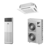
Daikin SkyAir Super Inverter 70 Service Manual (255 pages)
Split System Air Conditioners D Series;
Brand:
Daikin
| Category:
Air Conditioner
| Size: 4.97 MB
Table of Contents
Table of Contents
2
Introduction
6
Safety Cautions
6
Caution in Repair
6
Cautions Regarding Products after Repair
7
Inspection after Repair
8
Using Icons
9
Using Icons List
9
Skyair Super Inverter 70 D Series Heat Pump
10
Part1 Model Name and Power Supply
12
Model Name and Power Supply
13
External Appearance
14
Part 2 Functions
16
List of Functions
17
Functions
17
Part 3 Specifications
20
Specifications
21
50Hz
21
60Hz
27
Comply with Australian Standard (50Hz)
29
Part 4 Remote Controller
32
Wired Remote Controller
33
Wired Remote Controller - NEW MODEL (for Cooling Only and Heat-Pump Model)
33
Installation
35
Wireless Remote Controller
37
Part 5 Field Piping and Wiring
40
Field Piping and Wiring
41
Precautions
41
Field Piping
44
Field Wiring
46
Part 6 Field Setting
48
Method of Field Set (Reset after Maintenance Inspection/Repair)
49
Explanation
49
Field Setting
50
Wireless Remote Controller
51
Initial Setting Contents
52
Local Setting Mode no
53
Detailed Explanation of Setting Modes
55
Setting of Air Flow Direction Adjustment Range
56
Fan Speed off When Thermostat Is off
57
Centralized Group No. Setting
61
Settings Concerning Maintenance
62
Indoor Unit PCB
62
Outdoor Unit Switches / Setting Jumper
66
Existence of DIP Switch, Jumper and BS
69
Reference Table
69
Initial DIP Switch Setting List (Factory Set)
71
Emergency Operation
72
Maintenance Mode Setting
73
Part 7 Function and Operation
74
Function of Main Components and Thermistors
75
Function Outline
77
Indoor Unit
77
Outdoor Unit
78
Electric Function Parts
80
Indoor Unit
80
Outdoor Unit
81
Function Details
83
Indoor Unit
83
Inverter Outdoor Unit (R-407C) (RZP71 ~ 140D)
91
Simulated Operation Function
92
Starting Control
93
Crankcase Heater Control
96
Low Pressure Protection Control
97
High Pressure Protection Control
97
Discharge Pipe Temperature Protection Control
98
Inverter Current Protection Control
99
Control by Inverter Fin Temperature
99
Protection Control by Overall Current
100
Defrost Control
102
Defrost Starting Condition
102
Defrost Condition
102
Pump down Residual Operation
103
Indoor Unit Fan Control
104
Operation Range
107
Operation Limits
107
Part 8 Troubleshooting
108
Maintenance Inspections
110
Optimal Operation Condition
110
Cautions in Handling New Refrigerant
113
How to Handle Request for Maintenance
115
Flow Chart
115
Troubleshooting Based on Equipment Condition
116
Equipment Does Not Operate
117
Indoor Fan Operates, but Compressor Does Not
118
Sie25
119
Cooling/Heating Operation Starts but Stops Immediately
120
After Equipment Shuts Down, It Cannot be Restarted for a While
121
Equipment Operates but Does Not Provide Cooling
122
Equipment Operates but Does Not Provide Heating
124
Equipment Discharges White Mist
125
Equipment Produces Loud Noise or Shakes
126
Equipment Discharges Dust
127
Remote Controller LCD Displays "88
128
Swing Flap Does Not Operate
129
Procedure of Self-Diagnosis by Remote Controller
130
The INSPECTION/TEST Button
130
Self-Diagnosis by Wired Remote Controller
131
Fault Diagnosis by Wireless Remote Controller
132
Remote Controller Display Malfunction Code and Contents
134
Procedure of Self-Diagnosis by LED
136
Troubleshooting by LED on the Indoor Unit's
136
Troubleshooting by LED on Inverter Outdoor Unit PCB
137
Troubleshooting by Remote Controller Display / LED Display
139
Explanation for Symbols
139
Malfunction Code and LED Display Table
140
Failure of Indoor Unit PC Board
143
Malfunction of Drain Water Level System (Float Type)
144
Failure of Drain System
146
Indoor Unit Fan Motor Lock
147
Malfunction of Indoor Unit Fan Motor
148
Troubleshooting
149
Swing Flap Motor Malfunction / Lock
150
Failure of Capacity Setting
152
Malfunction of Heat Exchange Temperature Sensor System
153
Malfunction of Suction Air Temperature Sensor System
154
Malfunction of Remote Controller Air Thermistor
155
Malfunction of Moisture Sensor System
156
Actuation of Protection Device
157
Failure of Outdoor Unit PC Board
158
Abnormal High Pressure Level
159
Low Pressure System (LPS) Malfunction
161
Compressor Motor Lock
162
Malfunction of Outdoor Unit Fan Motor
164
Malfunction of Electronic Expansion Valve
165
Malfunction of Discharge Pipe Temperature
167
Malfunction of High Pressure Switch System
169
Malfunction of Outdoor Fan Motor Signal
170
Malfunction of Thermistor System
171
Malfunction of Suction Pipe Pressure Sensor
172
Radiation Fin Temperature Increased
173
DC Output Overcurrent (Instantaneous)
174
Electronic Thermal (Time Lag)
176
Stall Prevention (Time Lag)
178
Malfunction of Transmission System (between Control PCB and Inverter PCB)
180
Open Phase
182
Malfunction of Radiator Fin Temperature Thermistor
184
Malfunction of Radiator Fin Temperature Thermistor
185
Failure of Capacity Setting
186
Gas Shortage (Malfunction)
187
Abnormal Power Supply Voltage
188
Malfunction of Transmission (between Indoor and Outdoor Unit)
190
Malfunction of Transmission
190
Malfunction of Transmission (between Indoor Unit and Remote Controller)
192
Between Indoor Unit and Remote Controller
192
Transmission Error between Main Remote Controller and Sub Remote Controller
193
Malfunction of Field Setting Switch
194
Centralized Address Setting Error
196
Part 9 Removal Procedure
204
Fhycp71~140D
205
Removal of Suction Grille
205
Removal of Air Filter
206
Removal of Decoration Panel
207
Removal of Horizontal Blade
209
Removal of Swing Motor
210
Removal of Switch Box
212
Removal of PC Board
214
Removal of Humidity Sensor and Air Temperature Thermistor
216
Removal of Fan Motor
217
Removal of Drain Pan, Drain Pump, Float Switch
219
Removal of Heat Exchanger Temperature Thermistor
221
Rzp71~140D
222
Removal of Outside Panels
222
Removal of Propeller Fan and Fan Motor
224
Removal of PC Board
225
Removal of Switch Box (A)
227
Removal of Switch Box (B)
228
Removal of Compressor(for RZP71D)
229
Removal of Compressor (for RZP71D)
229
Removal of Compressor(for RZP100~140D)
230
Removal of Compressor (for RZP100~140D)
230
Removal of Four Way Valve
232
Removal of Solenoid Valve and Motorized Valve (for RZP71D)
233
Removal of Solenoid Valve and Motorized Valve
233
Removal of Solenoid Valve and Motorized Valve (for RZP100~140D)
234
(For RZP100~140D)
234
Removal of Pressure Switch and Pressure Sensor
235
Part 10 Appendix
236
Piping Diagrams
237
Pair System
237
Twin System
238
Wiring Diagrams
239
Indoor Units
239
Outdoor Units
243
Index
248
Drawings & Flow Charts
252
Advertisement
Advertisement
Related Products
Daikin SkyAirFCQN-KVEA
Daikin SKYAIR
Daikin SkyAir RZQ-P Series
Daikin SkyAir RZR-P Series
Daikin SkyAir RZQ18PVJU9
Daikin SkyAir RZQ24PVJU9
Daikin SkyAir RZR-TA Series
Daikin SkyAir RZQ-TA Series
Daikin SkyAir FBQ Series
Daikin SkyAir FTQ Series
Daikin Categories
Air Conditioner
Heat Pump
Remote Control
Chiller
Fan
More Daikin Manuals
Login
Sign In
OR
Sign in with Facebook
Sign in with Google
Upload manual
Upload from disk
Upload from URL