Daikin SkyAir RZQ-P Series Service Manual
Cooling only / heat pump
Hide thumbs
Also See for SkyAir RZQ-P Series:
- Engineering data (238 pages) ,
- Service manual (202 pages)

Related Manuals for Daikin SkyAir RZQ-P Series


Summary of Contents for Daikin SkyAir RZQ-P Series
- Page 1 SiUS28-902_B Service Manual RZR-P, RZQ-P(9) Series Cooling Only / Heat Pump R-410A 60Hz...
-
Page 2: Table Of Contents
SiUS28-902_B RZR-P, RZQ-P(9) Series Cooling Only / Heat Pump R-410A 60Hz ED Reference For items below, please refer to Engineering Data. Item ED No. Page Remarks Specification - Cooling Only EDUS281104 p. 7-11 Specification - Heat Pump EDUS281104 p. 12-16 Option List EDUS281104 p. - Page 3 SiUS28-902_B Part 2 Refrigerant Circuit ............. 5 1. Refrigerant Circuit ...................6 1.1 RZR18 / 24 / 30PVJU RZQ18 / 24 / 30PVJU(9) ................6 1.2 RZR36 / 42PVJU RZQ36 / 42PVJU(9) ................. 8 2. Functional Parts Layout ................10 2.1 RZR18 / 24 / 30PVJU RZQ18 / 24 / 30PVJU (9) ...............
- Page 4 SiUS28-902_B Part 4 Test Operation ..............42 1. Test Operation ..................43 1.1 Procedure and Outline ................43 1.2 Operation when Power is Turned ON ............ 46 2. Outdoor Unit PCB Layout ..............47 3. Field Setting ..................48 3.1 Field Setting from Remote Controller............. 48 3.2 Field Setting from Remote Controller (Indoor Unit)........
- Page 5 SiUS28-902_B 3.24 Outdoor Air Thermistor Abnormality ............ 119 3.25 Discharge Pipe Thermistor Abnormality..........120 3.26 Suction Pipe Thermistor Abnormality........... 121 3.27 Outdoor Unit Heat Exchanger Thermistor Abnormality......122 3.28 High Pressure Sensor Abnormality ............123 3.29 Low Pressure Sensor Abnormality............125 3.30 Outdoor Unit PCB Abnormality ............
-
Page 6: Safety Considerations
Safety Considerations SiUS28-902_B 1. Safety Considerations Read these SAFETY CONSIDERATIONS carefully before performing any repair work. Comply with these safety symbols without fail.Meanings of DANGER, WARNING, CAUTION, and NOTE Symbols: Meanings of DANGER, WARNING, CAUTION, and NOTE Symbols: DANGER ....Indicates an imminently hazardous situation which, if not avoided, will result in death or serious injury. WARNING .... -
Page 7: Safety Considerations For Users
SiUS28-902_B Safety Considerations pump-down and close the service valve to prevent the refrigerant gas from leaking into the room. The refrigerant gas itself is harmless, but it may generate toxic gases if it comes into contact with flames. • Do not repair the electrical components with wet hands. Working on the equipment with wet hands may cause an electrical shock. -
Page 8: Preface
Thank you for your continued patronage of Daikin products. This is the new service manual for Daikin's Year 2011 SkyAir series Cooling Only and Heat Pump System. Daikin offers a wide range of models to respond to building and office air conditioning needs. -
Page 9: General Information
SiUS28-902_B Part 1 General Information 1. Model Names and Power Supply............2 1.1 Cooling Only .................... 2 1.2 Heat Pump ....................2 2. External Appearance ................3 2.1 Indoor Units....................3 2.2 Remote Controller ..................4 2.3 Outdoor Units ................... 4 General Information... -
Page 10: Model Names And Power Supply
Model Names and Power Supply SiUS28-902_B 1. Model Names and Power Supply Cooling Only Indoor unit Outdoor unit Power supply, Compatibility symbol FCQ18PVJU RZR18PVJU* FCQ24PVJU RZR24PVJU* Ceiling mounted cassette type FCQ30PVJU RZR30PVJU* (Multi flow) FCQ36MVJU RZR36PVJU* FCQ42MVJU RZR42PVJU* FHQ18PVJU RZR18PVJU* FHQ24PVJU RZR24PVJU* Ceiling suspended type... -
Page 11: External Appearance
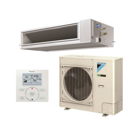
SiUS28-902_B External Appearance 2. External Appearance Indoor Units Ceiling Mounted Cassette Type (Multi Flow) FCQ18PVJU FCQ24PVJU FCQ30PVJU FCQ36MVJU FCQ42MVJU Ceiling Suspended Type FHQ18PVJU FHQ24PVJU FHQ30PVJU FHQ36MVJU FHQ42MVJU Wall Mounted Type FAQ18PVJU FAQ24PVJU Air Handling Unit FTQ18PAVJU FTQ24PAVJU General Information... -
Page 12: Remote Controller
External Appearance SiUS28-902_B Remote Controller Wired Type BRC1D71 BRC1E71 Outdoor Units RZR18PVJU RZR24PVJU RZR30PVJU RZQ18PVJU9 RZQ24PVJU9 RZQ30PVJU RZR36PVJU RZR42PVJU RZQ36PVJU9 RZQ42PVJU9 General Information... -
Page 13: Refrigerant Circuit
SiUS28-902_B Part 2 Refrigerant Circuit 1. Refrigerant Circuit ...................6 1.1 RZR18 / 24 / 30PVJU RZQ18 / 24 / 30PVJU(9) ................6 1.2 RZR36 / 42PVJU RZQ36 / 42PVJU(9) ................. 8 2. Functional Parts Layout ................10 2.1 RZR18 / 24 / 30PVJU RZQ18 / 24 / 30PVJU (9) ............... -
Page 14: Refrigerant Circuit
Refrigerant Circuit SiUS28-902_B 1. Refrigerant Circuit RZR18 / 24 / 30PVJU RZQ18 / 24 / 30PVJU(9) No. in refrigerant Symbol Name Major Function system diagram Inverter compressor is operated on frequencies between 52 Hz and 177 Hz by using Inverter compressor (INV.) the inverter. - Page 15 SiUS28-902_B Refrigerant Circuit Electronic Filter Filter Outdoor heat exchanger Pressure regulating valve Four-way valve Fusible plug R10T Solenoid Solenoid Filter valve Muffler valve Indoor heat exchanger Check valve Capillary tube S1NPH pressure High sensor pressure S1NPL sensor S1PH Service port Electronic High (5/16"...
-
Page 16: Rzr36 / 42Pvju Rzq36 / 42Pvju(9)
Refrigerant Circuit SiUS28-902_B RZR36 / 42PVJU RZQ36 / 42PVJU(9) No. in refrigerant Symbol Name Major Function system diagram Inverter compressor is operated on frequencies between 36 Hz and 195 Hz by using Inverter compressor (INV) the inverter. 31 steps Because the system is of an air heat exchange type, the fan is operated at 8-step Inverter fan rotation speed by using the inverter. - Page 17 SiUS28-902_B Refrigerant Circuit Electronic expansion valve Double pipe Electronic Fusible heat exchanger expansion valve plug Filter Heat exchanger Pressure regulating valve Service port Four-way valve High pressure Service port sensor Low pressure S1NPH FIN TH Capillary Solenoid Capillary Filter Filter Capillary Solenoid Compressor...
-
Page 18: Functional Parts Layout
Functional Parts Layout SiUS28-902_B 2. Functional Parts Layout RZR18 / 24 / 30PVJU RZQ18 / 24 / 30PVJU (9) LEAD WIRE (HIGH VOLTAGE) LEAD WIRE (LOW VOLTAGE) LEAD WIRE (HIGH VOLTAGE) LEAD WIRE (LOW VOLTAGE) LEAD WIRE (HIGH VOLTAGE) LEAD WIRE (LOW VOLTAGE) THERMAL INSULATION TUBE... -
Page 19: Function
SiUS28-902_B Part 3 Function 1. Operation Mode ..................12 2. Basic Control..................13 2.1 Normal Operation................... 13 2.2 Compressor PI Control ................14 2.3 Electronic Expansion Valve PI Control ..........15 2.4 Cooling Operation Fan Control .............. 16 3. Special Control..................17 3.1 Startup Control ..................17 3.2 Oil Return Operation ................ -
Page 20: Operation Mode
Operation Mode SiUS28-902_B 1. Operation Mode Operation in stop mode Indoor unit stop or Indoor unit thermostat ON thermostat OFF Error/Standby Restart standby Pressure (Compressor stop) equalization prior to startup Error/ Standby Indoor unit stop or thermostat OFF Startup control •... -
Page 21: Basic Control
SiUS28-902_B Basic Control 2. Basic Control Normal Operation Cooling Electric Symbol Operation Parts Name Symbol Remarks RZR18/24/30P RZR36/42P RZR18/24/30P RZR36/42P RZQ18/24/30P RZQ36/42P RZQ18/24/30P RZQ36/42P Used for high pressure protection control, low pressure protection control, discharge pipe Compressor Compressor Compressor (INV.) temperature protection PI control... -
Page 22: Compressor Pi Control
Basic Control SiUS28-902_B Compressor PI Control Compressor PI Control Low pressure equivalent saturation temperature TeS: Target Te value (Varies depending on Te setting, operating frequency, etc.) High pressure equivalent saturation temperature TcS: Target Tc value (Varies depending on Tc setting, operating frequency, etc.) Carries out the compressor capacity PI control to maintain Te at constant during cooling operation and Tc at constant during heating operation to ensure stable unit performance. -
Page 23: Electronic Expansion Valve Pi Control
SiUS28-902_B Basic Control RZR36/42P, RZQ36/42P INV(Fullload) INV(Unload) INV(Fullload) INV(Unload) INV(Fullload) INV(Unload) 36.0Hz 80.0Hz 140.0Hz 39.0Hz 86.0Hz 146.0Hz 43.0Hz 92.0Hz 152.0Hz 47.0Hz 98.0Hz 158.0Hz 52.0Hz 104.0Hz 164.0Hz 52.0Hz 57.0Hz 110.0Hz 170.0Hz 57.0Hz 64.0Hz 116.0Hz 175.0Hz 62.0Hz 71.0Hz 122.0Hz 180.0Hz 68.0Hz 78.0Hz 128.0Hz 185.0Hz 74.0Hz... -
Page 24: Cooling Operation Fan Control
Basic Control SiUS28-902_B Cooling Operation Fan Control In cooling operation with low outdoor air temperature, this control is used to provide the adequate amount of circulation air with liquid pressure secured by high pressure control using outdoor unit fan. Pc: High pressure sensor detection value Pc >... -
Page 25: Special Control
SiUS28-902_B Special Control 3. Special Control Startup Control On activation, following control is performed to lighten load of the compressor by back liquid and the like. Also, the position of the four-way valve is defined. Pc: High pressure sensor detection value Pe: Low pressure sensor detection value 3.1.1 Startup Control in Cooling Actuator... -
Page 26: Oil Return Operation
Special Control SiUS28-902_B Oil Return Operation Oil flown from the compressor to the side of system is collected by oil-returning operation, in case of that oil in the compressor runs down. 3.2.1 Oil Return Operation in Cooling Tc: High pressure equivalent saturation temperature Te: Low pressure equivalent saturation temperature Ts: Suction pipe temperature detected by thermistor [Conditions to start]... - Page 27 SiUS28-902_B Special Control 3.2.2 Oil Return Operation in Heating Pc: High pressure sensor detection value Pe: Low pressure sensor detection value Tc: High pressure equivalent saturation temperature Te: Low pressure equivalent saturation temperature Ts: Suction pipe temperature detected by thermistor [Conditions to start] The heating oil-returning operation is started referring following conditions.
-
Page 28: Defrosting Operation
Special Control SiUS28-902_B Defrosting Operation Pc: High pressure sensor detection value Pe: Low pressure sensor detection value Tc: High pressure equivalent saturation temperature Te: Suction pipe equivalent saturation temperature The defrost operation is performed to solve frost on the outdoor unit heat exchanger when heating, and the heating capacity is recovered. -
Page 29: Pump Down Residual Operation
SiUS28-902_B Special Control Pump Down Residual Operation Pe: Low pressure sensor detection value Td: Discharge pipe temperature When activating compressor, if the liquid refrigerant remains in the heat-exchanger, the liquid enters into the compressor and dilutes oil therein resulting in decrease of lubricity. Therefore, the pump down residual operation is performed to collect the refrigerant in the heat- exchanger when the compressor is down. -
Page 30: Stopping Operation
Special Control SiUS28-902_B Stopping Operation Operation of the actuator when the system is down, is cleared up. 3.6.1 When System is in Stop Mode Actuator Operation Compressor Outdoor unit fan Four way valve Keep former condition. Main electronic expansion valve (EV1) 0 pls gas bypass valve (SVP) Receiver gas discharging valve (SVG) -
Page 31: Protection Control
SiUS28-902_B Protection Control 4. Protection Control High Pressure Protection Control Pc: High-pressure sensor detection value This high-pressure protection control is used to prevent the activation of protection devices due to abnormal increase of high pressure and to protect compressors against the transient increase of high pressure. -
Page 32: Low Pressure Protection Control
Protection Control SiUS28-902_B Low Pressure Protection Control Pe: Low-pressure sensor detection value This low-pressure protection control is used to protect compressors against the transient decrease of low pressure. [Cooling] Low pressure not limited < 36 psi > 57 psi Low pressure limited 57Hz <... -
Page 33: Discharge Pipe Protection Control
SiUS28-902_B Protection Control Discharge Pipe Protection Control HTdi: Value of INV. compressor discharge pipe temperature (Tdi) compensated with outdoor air temperature Tp: Value of compressor port temperature calculated by Tc and Te, and suction superheated degree. This discharge pipe protection control is used to protect the compressor internal temperature against an error or transient increase of discharge pipe temperature. -
Page 34: Inverter Protection Control
Protection Control SiUS28-902_B Inverter Protection Control Tb: Outdoor unit heat exchanger temperature Tfin: Radiation fin temperature Inverter current protection control and radiation fin temperature control are performed to prevent tripping due to an error, or transient inverter overcurrent, and radiation fin temperature increase. [Inverter overcurrent protection control] Not limited •... -
Page 35: Other Control
SiUS28-902_B Other Control 5. Other Control Heating Operation Prohibition Heating operation is prohibited above 82°FDB outdoor air temperature. 6. Outline of Control (Indoor Unit) Drain Pump Control The drain pump is controlled by the ON/OFF buttons (4 button (1) - (4) given in the figure below). - Page 36 Outline of Control (Indoor Unit) SiUS28-902_B 6.1.3 When the Float Switch is Tripped during Heating Operation: Remote controller " " flashing error stop Thermostat (running) Humidifier Reset Float switch Drain pump 5 min. 5 sec. 5 min. Note: During heating operation, if the float switch is not reset even after the 5 minutes operation, 5 seconds stop, 5 minutes operation cycle ends, operation continues until the switch is reset.
-
Page 37: Louver Control For Preventing Ceiling Dirt
SiUS28-902_B Outline of Control (Indoor Unit) Louver Control for Preventing Ceiling Dirt We have added a control feature that allows you to select the range of in which air direction can be adjusted in order to prevent the ceiling surrounding the air discharge outlet of ceiling mounted cassette type units from being soiled. -
Page 38: Room Temperature Thermistor In Remote Controller
Outline of Control (Indoor Unit) SiUS28-902_B Room Temperature Thermistor in Remote Controller Temperature is controlled by both the room temperature thermistor in remote controller and suction air thermistor () in the indoor unit. (This is however limited to when the field setting for the room temperature thermistor in remote controller is set to “Use.”) Note: When outdoor air is introduced to the air conditioner with mixed into indoor air, the room... - Page 39 SiUS28-902_B Outline of Control (Indoor Unit) Heating When heating, the hot air rises to the top of the room, resulting in the temperature being lower near the floor where the occupants are. When controlling by suction air thermistor () only, the unit may therefore be turned off by the thermostat before the lower part of the room reaches the set temperature.
-
Page 40: Freeze-Up Prevention
Outline of Control (Indoor Unit) SiUS28-902_B Freeze-up Prevention Freeze-up When the temperature detected by liquid pipe temperature thermistor of the indoor unit heat Prevention by Off exchanger drops too low, the unit enters freeze-up prevention operation in accordance with the following conditions, and is also set in accordance with the conditions given below. -
Page 41: View Of Operations Of Swing Flaps
SiUS28-902_B Outline of Control (Indoor Unit) View of Operations of Swing Flaps Swing flaps work as following. Flap Control Swinging Level Level Level Hot-start from defrosting Setting the wind direction Level Level Level Swinging Level Level Level Defrosting Setting the wind direction Level Level Level... -
Page 42: Hot Start Control (In Heating Operation Only)
Outline of Control (Indoor Unit) SiUS28-902_B Hot Start Control (In Heating Operation Only) FCQ, FHQ, FAQ At startup with thermostat ON or after the completion of defrosting in heating operation, the indoor unit fan is controlled to prevent cold air from blasting out and ensure startup capacity. [Detail of operation] When either the starting condition 1 or the starting condition 2 is established, the operations shown below will be conducted. - Page 43 SiUS28-902_B Outline of Control (Indoor Unit) FTQ At startup with thermostat ON or after the completion of defrosting in heating operation, the indoor unit fan is controlled to prevent cold air from blasting out and ensure startup capacity. [Detail of operation] When either the starting condition 1 or the starting condition 2 is established, the operations shown below will be conducted.
-
Page 44: Heater Control (Only For Ftq)
Outline of Control (Indoor Unit) SiUS28-902_B Heater Control (Only for FTQ) 6.7.1 Auxiliary Electric Heater If heating is insufficient in the heat pump system alone, an electrical heater is to be used as the auxiliary heater. The following shows the ON/OFF conditions for the electric heater. Fan H tap Thermostat OFF/Stop operation 120 seconds ∗2... - Page 45 SiUS28-902_B Outline of Control (Indoor Unit) Condition A • Thermostat step 2 = "ON" • Heating mode • Not during test operation • Not during control operation & • High pressure condition = "ON" ∗3 • Liquid pipe temperature condition = "ON" ∗4 •...
- Page 46 Outline of Control (Indoor Unit) SiUS28-902_B 6.7.2 Heat Pump Lockout Mode During heating operation, users can select an electrical heater for heating. For this, signals are sent using ABC terminal of outdoor unit PCB. When the hot-water heating signal is received from the outdoor unit PCB, heating operation is performed only with the heater as manual backup operation.
-
Page 47: Step Thermostat Processing (Only For Ftq)
SiUS28-902_B Outline of Control (Indoor Unit) Condition A • Heating mode • Thermostat step 1 = "ON" • Not during fan residual operation & • [Electrical heater setting] = "01" • [Electrical heater setting] = "03" & • Hot-water heater = "1" (ON) Condition B •... -
Page 48: Interlocked With External Equipment (Only For Ftq)
Outline of Control (Indoor Unit) SiUS28-902_B Interlocked with External Equipment (Only for FTQ) 6.9.1 Humidifier When a humidifier is connected onsite, the fan operates with the airflow rate set of the remote controller or with the H tap. • Remote control operation = ON &... - Page 49 SiUS28-902_B Outline of Control (Indoor Unit) 6.9.2 Economizer When indoor and outdoor temperatures are reversed, the compressor is stopped to let in the outdoor air to save energy. This operation is called economizer operation, and the equipment to detect indoor and outdoor temperatures and open and close the damper to perform this operation is called an economizer.
-
Page 50: Test Operation
SiUS28-902_B Part 4 Test Operation 1. Test Operation ..................43 1.1 Procedure and Outline ................43 1.2 Operation when Power is Turned ON ............ 46 2. Outdoor Unit PCB Layout ..............47 3. Field Setting ..................48 3.1 Field Setting from Remote Controller............. 48 3.2 Field Setting from Remote Controller (Indoor Unit)........ -
Page 51: Test Operation
SiUS28-902_B Test Operation 1. Test Operation Procedure and Outline Follow the following procedure to conduct the initial test operation after installation. 1.1.1 Check Work Prior to Turn Power Supply ON Is the power supply single-phase 208-230V / 60Hz? Check the below items. ... - Page 52 Test Operation SiUS28-902_B 1.1.3 Check Operation * During check operation, mount front panel to avoid the misjudging. * Check operation is mandatory for normal unit operation. (When the check operation is not executed, alarm code " " will be displayed.) ⎧...
- Page 53 SiUS28-902_B Test Operation 1.1.4 Confirmation on Normal Operation Conduct normal unit operation after the check operation has been completed. (When outdoor air temperature is 82°FDB or higher, the unit can not be operated with heating mode. See the installation manual attached.) ...
-
Page 54: Operation When Power Is Turned On
Test Operation SiUS28-902_B Operation when Power is Turned ON 1.2.1 When Turning ON Power First Time The unit cannot be run for up to 12 minutes to automatically set the master power and address (indoor-outdoor address, etc.). Status Outdoor unit Test lamp H2P .. -
Page 55: Outdoor Unit Pcb Layout
SiUS28-902_B Outdoor Unit PCB Layout 2. Outdoor Unit PCB Layout Outdoor unit PCB (2) Set mode display (LED) (A2P) DIP switches (3) Mode setting switch H1P H2P H3P H4P H5P H6P H7P (DS1-1 and DS1-2) MODE RETURN TEST RESET (4) DIP switch (1) Service monitor (A1P) Connection terminal for transmission use... -
Page 56: Field Setting
Field Setting SiUS28-902_B 3. Field Setting Field Setting from Remote Controller Individual function of indoor unit can be changed from the remote controller. At the time of installation or after service inspection / repair, make the local setting in accordance with the following description. - Page 57 SiUS28-902_B Field Setting BRC1E71 Press and hold Cancel button for <Basic screen> 4 seconds or more. Service settings menu is displayed. Select Field Settings in the Service Settings menu, and press Menu/OK button. Field settings screen is displayed. Press and hold Cancel button for 4 seconds or Highlight the mode, and select more during backlight lit.
- Page 58 Field Setting SiUS28-902_B Press Menu/OK button. Setting confirmation screen is displayed. <Setting confirmation screen> Select and press Menu/OK Field Settings button. Setting details are Save the settings? determined and field settings screen returns. Setting In the case of multiple setting changes, repeat “...
- Page 59 SiUS28-902_B Field Setting 3.1.2 Wireless Remote Controller BRC7C812 BRC7E83 BRC7E818 MODE NO. FIELD SET MODE SECOND CODE NO. FIRST CODE NO. 1, 6 1. When in the normal mode, press the button for 4 seconds or more, and operation then enters the “field setting mode.” 2.
-
Page 60: Field Setting From Remote Controller (Indoor Unit)
Field Setting SiUS28-902_B Field Setting from Remote Controller (Indoor Unit) 3.2.1 Setting Contents and Code No. : Factory setting Second Code No. First Code Mode No. Description of Setting Filter cleaning sign time Light Heavy — — 0 5 Filter dirt Light Heavy —... - Page 61 SiUS28-902_B Field Setting 3.2.2 Applicable Range of Field Setting Mode First Code No. Description of Setting Filter cleaning sign time — Filter dirt — — — Filter type — — — Filter cleaning sign time —...
- Page 62 Field Setting SiUS28-902_B 3.2.3 Detailed Explanation of Setting Modes Filter Sign Setting If switching the filter sign ON time, set as given in the table below. Filter Specs. Lighting interval of the filter sign (hours) First Code Second Mode No. Code No.
- Page 63 SiUS28-902_B Field Setting Auto Restart after Power Failure Reset For the air conditioners with no setting for the function, the units will be left in the stop condition when the power supply is reset automatically after power failure reset or the main power supply is turned on again after once turned off.
- Page 64 Field Setting SiUS28-902_B 3.2.4 Setting of Operation Control Mode from Remote Controller (Local Setting) The operation control mode is compatible with a variety of controls and operations by limiting the functions of the operation remote controller. Furthermore, operations such as remote controller ON/OFF can be limited in accordance with the combination conditions.
- Page 65 SiUS28-902_B Field Setting How to Select Whether operation by remote controller will be possible or not for turning ON/OFF, controlling Operation Mode temperature or setting operation mode is selected and decided by the operation mode given on the right edge of the table below. Example ON by remote OFF by remote...
-
Page 66: Field Setting From Outdoor Unit
Field Setting SiUS28-902_B Field Setting from Outdoor Unit 3.3.1 Setting by DIP Switches The following field settings are made by DIP switches on PCB. DIPswitch Setting item Description Setting Cool/Heat Used to set cool/heat changeover setting by remote DS1-1 changeover controller equipped with outdoor unit. - Page 67 SiUS28-902_B Field Setting Mode changing procedure Using the MODE button, the modes can be changed as follows. (Normal) Press and hold the BS1 Press the BS1(MODE) (MODE) for 5 seconds. 1 time. Monitor mode Setting mode 2 Setting mode 1 Press the BS1(MODE) 1 time.
- Page 68 Field Setting SiUS28-902_B a. “Setting mode 1” This mode is used to set and check the current operating conditions (Normal / Abnormal / In check operation) Normally, “Setting mode 1” is set. In case of other status, press MODE button (BS1) 1 time and set to “Setting mode 1”.
- Page 69 SiUS28-902_B Field Setting b. “Setting mode 2” Setting item Description Press and hold the MODE button (BS1) for 5 seconds and set to Indoor unit forced Allows forced operation of indoor unit fan while unit is “Setting mode 2”. fan H stopped.
- Page 70 Field Setting SiUS28-902_B k: ON h: OFF l: Blink Setting item display C/H selection Setting condition display MODE TEST Demand Setting item noise Master Slave Factory setting k h h h h h k Normal operation Indoor unit forced fan H k h h h h k h Indoor forced fan H...
- Page 71 SiUS28-902_B Field Setting k: ON h: OFF l: Blink c. Monitor mode LED display Setting item Data display l h h h h h h To enter the monitor mode, press Various settings See below the MODE button (BS1) when in l h h h k h k Number of connected indoor units Lower 6 digits...
-
Page 72: Detail Of Setting Mode
Field Setting SiUS28-902_B Detail of Setting Mode 3.4.1 Cool / Heat Mode Switching The Cool / Heat Mode switching is carried out by remote controller fitted to indoor unit. This setting is not required for normal operation. (Factory setting) 3.4.2 Setting of Low Noise Operation and Demand Operation Setting of Low Noise Operation By connecting the external contact input to the low noise input of the outdoor unit external control adaptor (optional), you can lower operating noise by 2-3 dB. - Page 73 SiUS28-902_B Field Setting 3. If necessary, while in "Setting mode 2", select the setting condition (i.e., "06:00", "07:00", or "08:00") for set item No. 27 (Setting of end time of low night noise operation). (Use the end time as a guide since it is estimated according to outdoor temperatures.) 4.
- Page 74 Field Setting SiUS28-902_B 3.4.3 Setting of Demand Operation By connecting the external contact input to the demand input of the outdoor unit external control adaptor (optional), the power consumption of unit operation can be saved suppressing the compressor operating condition. Setting content Setting method External control...
- Page 75 SiUS28-902_B Field Setting Image of operation in the case of A Power consumption The power Rated power consumption consumption during 80 % of rated power consumption Demand level 1 instructing Demand level 2 instructing Demand level 3 instructing the demand level 1 70 % of rated power consumption instructing can be 60 % of rated power consumption...
- Page 76 Field Setting SiUS28-902_B Detailed Setting Procedure of Quiet Operation and Demand Control 1. Setting mode 1 (H1P off) (1) In setting mode 2, press the BS1 (MODE button) 1 time. Setting mode 1 is entered and H1P off. During the setting mode 1 is displayed, “In quiet operation” and “In demand control” are displayed.
- Page 77 SiUS28-902_B Field Setting 3.4.4 Setting of Refrigerant Recovery Mode When carrying out the refrigerant collection on site, fully open the respective electronic expansion valve of indoor and outdoor units. Both the outdoor unit and the indoor unit cannot be operated at this time. [Operation procedure] (1) In setting mode 2 with units in stop mode, set “Refrigerant Recovery / Vacuuming mode”...
- Page 78 Field Setting SiUS28-902_B 3.4.6 Check Operation To prevent any trouble in the period of installation at site, the system is provided with a test operation mode enabling check for incorrect wiring, stop valve left in closed, and judgement of piping length. CHECK OPERATION FUNCTION LED display (H1P~H7P) ( BLINK...
-
Page 79: Service Diagnosis
SiUS28-902_B Part 5 Service Diagnosis 1. Symptom-based Troubleshooting ............73 2. Troubleshooting by Remote Controller ..........76 2.1 The INSPECTION / TEST Button ............76 2.2 Self-diagnosis by Wired Remote Controller ........... 77 2.3 Self-diagnosis by Wireless Remote Controller........79 2.4 Inspection Mode..................81 2.5 Remote Controller Service Mode ............ - Page 80 SiUS28-902_B 3.33 Electronic Thermal (Time Lag)............. 130 3.34 Inverter Startup Error ................132 3.35 Transmission Error (between Control and Inverter PCB)..... 133 3.36 Radiation Fin Thermistor Abnormality..........134 3.37 Refrigerant Shortage................135 3.38 Power Supply Voltage Abnormality............136 3.39 Check Operation not Executed ............138 3.40 Transmission Error (between Indoor Units and Outdoor Units) ...
-
Page 81: Symptom-Based Troubleshooting
SiUS28-902_B Symptom-based Troubleshooting 1. Symptom-based Troubleshooting Symptom Supposed Cause Countermeasure The system does not start operation at all. Blowout of fuse(s) Turn Off the power supply and then replace the fuse(s). Cutout of breaker(s) • If the knob of any breaker is in its OFF position, turn ON the power supply. - Page 82 Symptom-based Troubleshooting SiUS28-902_B Symptom Supposed Cause Countermeasure COOL-HEAT The remote controller displays This remote controller has no Use a remote controller with selection is "UNDER CENTRALIZED option to select cooling operation. option to select cooling operation. disabled. CONTROL". The remote controller displays COOL-HEAT selection is made Use the COOL-HEAT selection "UNDER CENTRALIZED...
- Page 83 SiUS28-902_B Symptom-based Troubleshooting Symptom Supposed Cause Countermeasure 11 The system <Indoor unit> Operating sounds of the Normal operation. produces Immediately after turning ON electronic expansion valve of the This sound lowers after sounds. the power supply, indoor unit indoor unit. approximately 1 minute.
-
Page 84: Troubleshooting By Remote Controller
Troubleshooting by Remote Controller SiUS28-902_B 2. Troubleshooting by Remote Controller The INSPECTION / TEST Button 2.1.1 BRC1D71 The following modes can be selected by using the [Inspection/Test Operation] button on the remote control. Depress the Inspection/Test Operation button for more than 4 seconds. Indoor unit settings can be made Service data can be obtained. -
Page 85: Self-Diagnosis By Wired Remote Controller
SiUS28-902_B Troubleshooting by Remote Controller Self-diagnosis by Wired Remote Controller 2.2.1 BRC1D71 If operation stops due to error, the remote controller’s operation LED blinks, and error code is displayed. (Even if stop operation is carried out, error contents are displayed when the inspection mode is entered.) The error code enables you to tell what kind of error caused operation to stop. - Page 86 Troubleshooting by Remote Controller SiUS28-902_B 2.2.2 BRC1E71 The following will be displayed on the screen when an error (or a warning) occurs during operation. Check the error code and take the corrective action specified for the particular model. Screen Operation lamp (1) Checking an error or warning Operation Status Display...
-
Page 87: Self-Diagnosis By Wireless Remote Controller
SiUS28-902_B Troubleshooting by Remote Controller Self-diagnosis by Wireless Remote Controller In the Case of If equipment stops due to an error, the operation indicating LED on the light reception section BRC7C Type flashes. The error code can be determined by following the procedure described below. (The error code BRC7E Type is displayed when an operation error has occurred. - Page 88 Troubleshooting by Remote Controller SiUS28-902_B Normal status Enters inspection mode from normal status when the INSPECTION/ TEST button is pressed. 1 Press INSPECTION/TEST button. If no button is pressed for 1 minute, equipment returns to normal status. Press MODE selector When MODE selector button.
-
Page 89: Inspection Mode
SiUS28-902_B Troubleshooting by Remote Controller Inspection Mode Unit Error code Inspection Normal display (No display) Error code blinks when an error occurs. Inspection/test 0 7 1... Capacity code Press the button. operation F... Indoor unit system code C... Indoor unit type code J... -
Page 90: Remote Controller Service Mode
Troubleshooting by Remote Controller SiUS28-902_B Remote Controller Service Mode 2.5.1 BRC1D71 How to Enter the Service Mode Field setting Normal operation Service mode mode mode Press the button for 4 seconds or more. Press the button for 4 seconds or more. TEST TEST Service Mode... - Page 91 SiUS28-902_B Troubleshooting by Remote Controller Mode Function Contents and operation method Remote controller display example Error history display Display error history. The history No. can be changed with the Unit 1 button. Error code 2-U4 Error code History No: 1 - 9 1: Latest Display of sensor Display various types of data.
- Page 92 Troubleshooting by Remote Controller SiUS28-902_B 2.5.2 BRC1E71 Operating the remote controller allows service data to be acquired and various services to be set. Basic screen is displayed. Press Cancel Press button. Cancel Press and hold Cancel button button for 4 seconds or more. once.
- Page 93 SiUS28-902_B Troubleshooting by Remote Controller Maintenance Menu Item 2 Remarks 3. Indoor Unit Status 10.FLOAT 11.T1/T2 12.Unit No. Select the Unit No. you want to check. SkyAir 13.Th1 Suction air thermistor 14.Th2 Heat exchanger thermistor 15.Th3 — 16.Th4 Discharge air thermistor 17.Th5 —...
-
Page 94: Error Codes And Description
Troubleshooting by Remote Controller SiUS28-902_B Error Codes and Description Error code Contents of Error Page Referred Indoor Unit External Protection Device Abnormality PCB Abnormality Drain Water Level System Abnormality Indoor Unit Fan Motor Abnormality Swing Flap Motor Abnormality / Lock Electronic Expansion Valve Coil Abnormality Drain System Abnormality Capacity Setting Device Abnormality... - Page 95 SiUS28-902_B Troubleshooting by Remote Controller Error Code Indication by Outdoor Unit PCB <Monitor mode> Contents of Error To enter the monitor mode, press the Error code MODE (BS1) button when in In-phase error of DIII-Net Detection of DIII-Net “Setting mode 1”. Discharge pressure Abnormality HPS activated Suction pressure Abnormality...
- Page 96 Troubleshooting by Remote Controller SiUS28-902_B k: ON h: OFF l: Blink Confirmation of Error 1 Confirmation of Error 2 Confirmation of Error 3 Confirmation of Error 4 Error Code H1P H2P H3P H4P H5P H6P H7P H1P H2P H3P H4P H5P H6P H7P H1P H2P H3P H4P H5P H6P H7P H1P H2P H3P H4P H5P H6P H7P 1 1 1...
-
Page 97: Troubleshooting By Indication On The Remote Controller
SiUS28-902_B Troubleshooting by Indication on the Remote Controller 3. Troubleshooting by Indication on the Remote Controller External Protection Device Abnormality Remote Controller Display Applicable All indoor models Models Method of Error Detect open or short circuit between external input terminals in indoor unit. Detection Error Decision When an open circuit occurs between external input terminals with the remote controller set to... -
Page 98: Pcb Abnormality
Troubleshooting by Indication on the Remote Controller SiUS28-902_B PCB Abnormality Remote Controller Display Applicable All indoor models Models Method of Error Check data from E²PROM. Detection Error Decision When data could not be correctly received from the E²PROM Conditions E²PROM: Type of nonvolatile memory. Maintains memory contents even when the power supply is turned OFF. -
Page 99: Drain Water Level System Abnormality
SiUS28-902_B Troubleshooting by Indication on the Remote Controller Drain Water Level System Abnormality Remote Controller Display Applicable FCQ, FHQ (Option), FAQ (Option), FTQ Models Method of Error By float switch OFF detection Detection Error Decision When rise of water level is not a condition and the float switch goes OFF Conditions ... - Page 100 Troubleshooting by Indication on the Remote Controller SiUS28-902_B For FTQ Connect a short circuit connector () For FCQ, FHQ, FAQ Is power supply 208~230V provided? Provide 208~230V power supply. A short circuit The float switch is connector is connected to connected to the connector (*) of Connect either a short circuit the connector (*).
-
Page 101: Indoor Unit Fan Motor Abnormality
SiUS28-902_B Troubleshooting by Indication on the Remote Controller Indoor Unit Fan Motor Abnormality Remote Controller Display Applicable FCQ, FHQ, FAQ, FTQ Models Method of Error Detection by failure of signal for detecting number of turns to come from the fan motor Detection Error Decision When revolutions cannot be detected even when output voltage to the fan is maximum... -
Page 102: Swing Flap Motor Abnormality / Lock
Troubleshooting by Indication on the Remote Controller SiUS28-902_B Swing Flap Motor Abnormality / Lock Remote Controller Display Applicable FCQ, FHQ, FAQ Models Method of Error Utilizes ON/OFF of the limit switch when the motor turns. Detection Error Decision When ON/OFF of the micro-switch for positioning cannot be reversed even though the swing Conditions flap motor is energized for a specified amount of time (about 30 seconds). - Page 103 SiUS28-902_B Troubleshooting by Indication on the Remote Controller Troubleshooting Be sure to turn off the power switch before connecting or disconnecting Caution the connector or parts may be damaged. Is power supply 208~230V provided? Provide 208~230V power supply. Indoor unit is a model equipped with a swing Replace the indoor unit PCB.
-
Page 104: Electronic Expansion Valve Coil Abnormality
Troubleshooting by Indication on the Remote Controller SiUS28-902_B Electronic Expansion Valve Coil Abnormality Remote Controller Display Applicable FCQ, FHQ, FAQ, FTQ Models Method of Error Check the coil condition of electronic expansion valve by using micro-computer. Detection Error Decision Pin input for electronic expansion valve coil is abnormal when initializing micro-computer. Conditions ... - Page 105 SiUS28-902_B Troubleshooting by Indication on the Remote Controller 1: Coil check method for the electronic expansion valve coil Discount the electronic expansion valve from the PCB and check the continuity between the connector pins. (Normal) Pin No. 1. White 2. Yellow 3.
-
Page 106: Drain System Abnormality
Troubleshooting by Indication on the Remote Controller SiUS28-902_B Drain System Abnormality Remote Controller Display Applicable FCQ, FHQ, FAQ, FTQ Models Method of Error Water leakage is detected based on float switch ON/OFF operation while the compressor is in Detection non-operation. Error Decision The float switch changes from ON to OFF while the compressor is OFF. -
Page 107: Capacity Setting Device Abnormality
SiUS28-902_B Troubleshooting by Indication on the Remote Controller Capacity Setting Device Abnormality Remote controller display Applicable FCQ, FHQ, FAQ, FTQ Models Method of Error Capacity is determined according to resistance of the capacity setting adaptor and the memory Detection inside the IC memory on the indoor unit PCB, and whether the value is normal or abnormal is determined. -
Page 108: Heat Exchanger (Liquid Pipe) Thermistor Abnormality
Troubleshooting by Indication on the Remote Controller SiUS28-902_B Heat Exchanger (Liquid pipe) Thermistor Abnormality Remote Controller Display Applicable All indoor models Models Method of Error The error is detected by temperature detected by heat exchanger thermistor. Detection Error Decision When the heat exchanger thermistor becomes disconnected or shorted while the unit is running Conditions ... -
Page 109: Heat Exchanger (Gas Pipe) Thermistor Abnormality
SiUS28-902_B Troubleshooting by Indication on the Remote Controller 3.10 Heat Exchanger (Gas Pipe) Thermistor Abnormality Remote Controller Display Applicable All indoor models Models Method of Error The error is detected by temperature detected by gas pipe thermistor. Detection Error Decision When the gas pipe thermistor becomes disconnected or shorted while the unit is running Conditions ... -
Page 110: Suction Air Thermistor Abnormality
Troubleshooting by Indication on the Remote Controller SiUS28-902_B 3.11 Suction Air Thermistor Abnormality Remote Controller Display Applicable FCQ, FHQ, FAQ Models Method of Error The error is detected by temperature detected by suction air temperature thermistor. Detection Error Decision When the suction air temperature thermistor becomes disconnected or shorted while the unit is Conditions running ... -
Page 111: Remote Sensor Abnormality
SiUS28-902_B Troubleshooting by Indication on the Remote Controller 3.12 Remote Sensor Abnormality Remote Controller Display Applicable Models Method of Error The error is detected out by temperature detected by remote sensor. Detection Error Decision When the remote sensor becomes disconnected or shorted while the unit is running Conditions ... -
Page 112: Room Temperature Thermistor In Remote Controller Abnormality
Troubleshooting by Indication on the Remote Controller SiUS28-902_B 3.13 Room Temperature Thermistor in Remote Controller Abnormality Remote Controller Display Applicable All indoor models Models Method of Error Error detection is carried out by temperature detected by room temperature thermistor in remote Detection controller. -
Page 113: Outdoor Unit Pcb Abnormality
SiUS28-902_B Troubleshooting by Indication on the Remote Controller 3.14 Outdoor Unit PCB Abnormality Remote Controller Display Applicable RZR, RZQ Models Method of Error Micro-computer checks whether E PROM is normal. Detection Error Decision When E PROM error when turning the power supply ON Conditions ... -
Page 114: High Pressure Abnormality
Troubleshooting by Indication on the Remote Controller SiUS28-902_B 3.15 High Pressure Abnormality Remote Controller Display Applicable RZR, RZQ Models Method of Error Abnormality is detected when the contact of the high pressure protection switch opens. Detection Error Decision Error is generated when the S1PH (High pressure switch) activation count reaches the number Conditions specific to the operation mode. - Page 115 SiUS28-902_B Troubleshooting by Indication on the Remote Controller Troubleshooting Be sure to turn off the power switch before connecting or disconnecting Caution the connector or parts may be damaged. Check for the points shown below. (1) Is the stop valve open? (2) Is the high pressure switch connector properly connected to the main PCB? (3) Does the high pressure switch have continuity?
-
Page 116: Actuation Of Low Pressure Sensor
Troubleshooting by Indication on the Remote Controller SiUS28-902_B 3.16 Actuation of Low Pressure Sensor Remote Controller Display Applicable RZR, RZQ Models Method of Error Abnormality is detected by the pressure value with the low pressure sensor. Detection Error Decision Error is generated when the low pressure is dropped during compressor operating. Conditions Operating pressure: 10 psi ... - Page 117 SiUS28-902_B Troubleshooting by Indication on the Remote Controller Troubleshooting Be sure to turn off the power switch before connecting or disconnecting Caution the connector or parts may be damaged. Is the stop Open the stop valve. valve open? (1) Mount a pressure gauge on the low pressure service port. (2) Connect the Service Checker.
-
Page 118: Inverter Compressor Motor Lock
Troubleshooting by Indication on the Remote Controller SiUS28-902_B 3.17 Inverter Compressor Motor Lock Remote Controller Display Applicable RZR, RZQ Models Method of Error Inverter PCB takes the position signal from UVW line connected between the inverter and Detection compressor, and the error is detected when any abnormality is observed in the phase-current waveform. - Page 119 SiUS28-902_B Troubleshooting by Indication on the Remote Controller Troubleshooting Be sure to turn off the power switch before connecting or disconnecting Caution the connector or parts may be damaged. Is the stop Local factor valve Open the stop valve. open? Are the relay wires Replace the relay wires and then to the compressor...
-
Page 120: Outdoor Unit Fan Motor Abnormality
Troubleshooting by Indication on the Remote Controller SiUS28-902_B 3.18 Outdoor Unit Fan Motor Abnormality Remote Controller Display Applicable RZR, RZQ Models Method of Error The error is detected according to the revolution speed detected by hall IC when the fan motor Detection runs. -
Page 121: Electronic Expansion Valve Coil Abnormality
SiUS28-902_B Troubleshooting by Indication on the Remote Controller 3.19 Electronic Expansion Valve Coil Abnormality Remote Controller Display Applicable RZR, RZQ Models Method of Error Check disconnection of connector Detection Check continuity of electronic expansion valve coil Error Decision Error is generated under no common power supply when the power is on. Conditions ... - Page 122 Troubleshooting by Indication on the Remote Controller SiUS28-902_B Troubleshooting Be sure to turn off the power switch before connecting or disconnecting Caution the connector or parts may be damaged. Turn power supply OFF, and turn power supply ON again. Return to normal? External factor (Noise, etc.).
-
Page 123: Discharge Pipe Temperature Control
SiUS28-902_B Troubleshooting by Indication on the Remote Controller 3.20 Discharge Pipe Temperature Control Remote Controller Display Applicable RZR, RZQ Models Method of Error Abnormality is detected according to the temperature detected by the discharge pipe Detection temperature thermistor. Error Decision When the discharge pipe temperature rises to an abnormally high level Conditions When the discharge pipe temperature rises suddenly... -
Page 124: Refrigerant Overcharged
Troubleshooting by Indication on the Remote Controller SiUS28-902_B 3.21 Refrigerant Overcharged Remote Controller Display Applicable RZR, RZQ Models Method of Error Excessive charging of refrigerant is detected by using the outdoor air temperature and heat Detection exchanger deicer temperature during check operation. Error Decision When the amount of refrigerant, which is calculated by using the outdoor air temperature and Conditions... -
Page 125: High Pressure Switch Abnormality
SiUS28-902_B Troubleshooting by Indication on the Remote Controller 3.22 High Pressure Switch Abnormality Remote Controller Display Applicable RZR, RZQ Models Method of Error The protection device circuit checks continuity in the high pressure switch. Detection Error Decision When there is no continuity in the high pressure switch during compressor stops operating Conditions ... -
Page 126: Outdoor Unit Fan Motor Signal Abnormality
Troubleshooting by Indication on the Remote Controller SiUS28-902_B 3.23 Outdoor Unit Fan Motor Signal Abnormality Remote Controller Display Applicable RZR, RZQ Models Method of Error Detection of abnormal signal from fan motor Detection Error Decision In case of detection of abnormal signal at starting fan motor Conditions ... -
Page 127: Outdoor Air Thermistor Abnormality
SiUS28-902_B Troubleshooting by Indication on the Remote Controller 3.24 Outdoor Air Thermistor Abnormality Remote Controller Display Applicable RZR, RZQ Models Method of Error The error is detected from the temperature detected by the outdoor air thermistor. Detection Error Decision When the outdoor air temperature thermistor has short circuit or open circuit Conditions ... -
Page 128: Discharge Pipe Thermistor Abnormality
Troubleshooting by Indication on the Remote Controller SiUS28-902_B 3.25 Discharge Pipe Thermistor Abnormality Remote Controller Display Applicable RZR, RZQ Models Method of Error The error is detected from the temperature detected by discharge pipe temperature thermistor. Detection Error Decision When a short circuit or an open circuit in the discharge pipe temperature thermistor is detected Conditions ... -
Page 129: Suction Pipe Thermistor Abnormality
SiUS28-902_B Troubleshooting by Indication on the Remote Controller 3.26 Suction Pipe Thermistor Abnormality Remote Controller Display Applicable RZR, RZQ Models Method of Error The error is detected from the temperature detected by the thermistor for suction pipe 1, 2. Detection Error Decision When a short circuit or an open circuit in the thermistor for suction pipe 1, 2 are detected Conditions... -
Page 130: Outdoor Unit Heat Exchanger Thermistor Abnormality
Troubleshooting by Indication on the Remote Controller SiUS28-902_B 3.27 Outdoor Unit Heat Exchanger Thermistor Abnormality Remote Controller Display Applicable RZR, RZQ Models Method of Error The error is detected from the temperature detected by the heat exchanger thermistor. Detection Error Decision When a short circuit or an open circuit in the heat exchanger thermistor is detected Conditions ... -
Page 131: High Pressure Sensor Abnormality
SiUS28-902_B Troubleshooting by Indication on the Remote Controller 3.28 High Pressure Sensor Abnormality Remote Controller Display Applicable RZR, RZQ Models Method of Error The error is detected from the pressure detected by the high pressure sensor. Detection Error Decision When the high pressure sensor is short circuit or open circuit Conditions ... - Page 132 Troubleshooting by Indication on the Remote Controller SiUS28-902_B Troubleshooting Be sure to turn off the power switch before connecting or disconnecting the connector or parts may be damaged. Caution The high pressure sensor is connected to X17A of outdoor unit PCB (A1P).
-
Page 133: Low Pressure Sensor Abnormality
SiUS28-902_B Troubleshooting by Indication on the Remote Controller 3.29 Low Pressure Sensor Abnormality Remote Controller Display Applicable RZR, RZQ Models Method of Error The error is detected from the pressure detected by the low pressure sensor. Detection Error Decision When the low pressure sensor is short circuit or open circuit Conditions ... - Page 134 Troubleshooting by Indication on the Remote Controller SiUS28-902_B Troubleshooting Be sure to turn off the power switch before connecting or disconnecting Caution the connector or parts may be damaged. The low pressure sensor is connected to X18A of Connect the low pressure sensor outdoor unit PCB property and turn ON again.
-
Page 135: Outdoor Unit Pcb Abnormality
SiUS28-902_B Troubleshooting by Indication on the Remote Controller 3.30 Outdoor Unit PCB Abnormality Remote Controller Display Applicable RZR, RZQ Models The error is detected by current value during waveform output before compressor startup. Method of Error The error is detected by current sensor value during synchronized operation at the time of Detection startup. -
Page 136: Radiation Fin Temperature Rise
Troubleshooting by Indication on the Remote Controller SiUS28-902_B 3.31 Radiation Fin Temperature Rise Remote Controller Display Applicable RZR, RZQ Models Method of Error Radiation fin temperature is detected by radiation fin thermistor. Detection Error Decision When the temperature of the inverter radiation fin rises abnormally due to faulty heat Conditions dissipation. -
Page 137: Momentary Overcurrent Of Inverter Compressor
SiUS28-902_B Troubleshooting by Indication on the Remote Controller 3.32 Momentary Overcurrent of Inverter Compressor Remote Controller Display Applicable RZR, RZQ Models Method of Error The error is detected from current flowing in the power transistor. Detection Error Decision When overcurrent flows in the power transistor Conditions (Instantaneous overcurrent also causes activation) ... -
Page 138: Electronic Thermal (Time Lag)
Troubleshooting by Indication on the Remote Controller SiUS28-902_B 3.33 Electronic Thermal (Time Lag) Remote Controller Display Applicable RZR, RZQ Models Method of Error The error is detected from the current flowing to power transistor into voltage with CT1 (DC Detection current sensor). - Page 139 SiUS28-902_B Troubleshooting by Indication on the Remote Controller Troubleshooting Be sure to turn off the power switch before connecting or disconnecting Caution the connector or parts may be damaged. Output current check secondary current of the inverter is higher than 14.8A, 260sec. Compressor overload.
-
Page 140: Inverter Startup Error
Troubleshooting by Indication on the Remote Controller SiUS28-902_B 3.34 Inverter Startup Error Remote Controller Display Applicable RZR, RZQ Models Method of Error The error is detected from current flowing in the power transistor. Detection Error Decision When overload in the compressor is detected during startup Conditions ... -
Page 141: Transmission Error (Between Control And Inverter Pcb)
SiUS28-902_B Troubleshooting by Indication on the Remote Controller 3.35 Transmission Error (between Control and Inverter PCB) Remote Controller Display Applicable RZR, RZQ Models Method of Error Check the communication state between inverter PCB and control PCB by micro-computer. Detection Error Decision When the correct communication is not conducted in certain period Conditions ... -
Page 142: Radiation Fin Thermistor Abnormality
Troubleshooting by Indication on the Remote Controller SiUS28-902_B 3.36 Radiation Fin Thermistor Abnormality Remote Controller Display Applicable RZR, RZQ Models Method of Error Detection by open or short circuit of the radiation fin thermistor during the compressor stops Detection operating. Error Decision When open or short circuit of the radiation fin thermistor is detected during the compressor Conditions... -
Page 143: Refrigerant Shortage
SiUS28-902_B Troubleshooting by Indication on the Remote Controller 3.37 Refrigerant Shortage Remote Controller Display Applicable RZR, RZQ Models Method of Error (In normal operation) Detection Gas shortage is detected according to the electronic expansion valve opening degree and measured temperatures and pressures. Error Decision (In cooling operation) When the electronic expansion valve opens fully and low pressure is below 14.5 psi... -
Page 144: Power Supply Voltage Abnormality
Troubleshooting by Indication on the Remote Controller SiUS28-902_B 3.38 Power Supply Voltage Abnormality Remote Controller Display Applicable RZR, RZQ Models Method of Error The error is detected according to the voltage of main circuit capacitor built in the inverter and Detection power supply voltage. - Page 145 SiUS28-902_B Troubleshooting by Indication on the Remote Controller Troubleshooting Be sure to turn off the power switch before connecting or disconnecting Caution the connector or parts may be damaged. Is the power Correct power supply. supply voltage 208~230V ±10%? CHECK 4 Check the inverter power transistor.
-
Page 146: Check Operation Not Executed
Troubleshooting by Indication on the Remote Controller SiUS28-902_B 3.39 Check Operation not Executed Remote Controller Display Applicable Models Method of Error Check operation is executed or not. Detection Error Decision The error is decided when the unit starts operation without check operation. Conditions ... -
Page 147: Transmission Error (Between Indoor Units And Outdoor Units)
SiUS28-902_B Troubleshooting by Indication on the Remote Controller 3.40 Transmission Error (between Indoor Units and Outdoor Units) Remote Controller Display Applicable FCQ, FHQ, FAQ, FTQ Models RZR, RZQ Method of Error Micro-computer checks if transmission between indoor and outdoor units is normal. Detection Error Decision When transmission is not carried out normally for a certain amount of time... - Page 148 Troubleshooting by Indication on the Remote Controller SiUS28-902_B Troubleshooting Be sure to turn off the power switch before connecting or disconnecting Caution the connector or parts may be damaged. Is the power supply voltage Request an 208-230V? improvement to make the power supply voltage fall within the standard range.
- Page 149 SiUS28-902_B Troubleshooting by Indication on the Remote Controller Check the resistance value of the outdoor fan motor. Is the resistance value of the Replace the outdoor unit outdoor unit fan motor fan motor. normal? Does the fuse (F6U) Replace the fuse. have continuity? Check the fan speed pulse.
-
Page 150: Transmission Error (Between Remote Controller And Indoor Unit)
Troubleshooting by Indication on the Remote Controller SiUS28-902_B 3.41 Transmission Error (between Remote Controller and Indoor Unit) Remote Controller Display Applicable All indoor unit models Models Method of Error In case of controlling with 2-remote controller, check the system using micro-computer is signal Detection transmission between indoor unit and remote controller (main and sub) is normal. -
Page 151: Transmission Error (Between Main And Sub Remote Controllers)
SiUS28-902_B Troubleshooting by Indication on the Remote Controller 3.42 Transmission Error (between Main and Sub Remote Controllers) Remote Controller Display Applicable All indoor models Models Method of Error In case of controlling with 2-remote controller, check the system using micro-computer if signal Detection transmission between indoor unit and remote controller (main and sub) is normal. -
Page 152: Transmission Error (Between Centralized Remote Controller And Indoor Unit)
Troubleshooting by Indication on the Remote Controller SiUS28-902_B 3.43 Transmission Error (between Centralized Remote Controller and Indoor Unit) Remote Controller Display Applicable FCQ, FHQ, FAQ, FTQ Centralized controller Models Method of Error Micro-computer checks if transmission between indoor unit and centralized remote controller is Detection normal. - Page 153 SiUS28-902_B Troubleshooting by Indication on the Remote Controller Troubleshooting Be sure to turn off the power switch before connecting or disconnecting Caution the connector or parts may be damaged. Has an indoor unit once connected been removed or Reset power supply its address simultaneously for all optional changed?
-
Page 154: System Is Not Set Yet
Troubleshooting by Indication on the Remote Controller SiUS28-902_B 3.44 System is not Set yet Remote Controller Display Applicable FCQ, FHQ, FAQ, FTQ Models RZQ18~30PVJU Method of Error On check operation, the capacity of indoor units in terms of transmission is not corresponding to Detection that of indoor units that have made changes in temperature. -
Page 155: Check
SiUS28-902_B Check 4. Check CHECK 1 Check for causes of rise in high pressure Referring to the Fault Tree Analysis (FTA) shown below, probe the error points. ←Check to be sure the stop valve is open. Stop valve closed Local High pipe ←Conduct visual checks for pipe conditions. - Page 156 Check SiUS28-902_B CHECK 2 Check for causes of drop in low pressure Referring to the Fault Tree Analysis (FTA) shown below, probe the error points. [In cooling] ←Are the electrical characteristics normal? Defective low pressure sensor Defective compressor ←Is the pressure value checked with the Service Checker Defective capacity Defective service monitor PCB...
- Page 157 SiUS28-902_B Check CHECK 3 Check for Fan Motor Connector (1) Turn the power supply off. (2) With the fan motor connector disconnected, measure the resistance between each pin, then make sure that the resistance is more than the value mentioned in the following table. 1 White Measurement point Judgement...
-
Page 158: Part 6
SiUS28-902_B Part 6 Appendix 1. Piping Diagrams..................151 1.1 Outdoor Unit..................151 1.2 Indoor Unit ................... 153 2. Wiring Diagrams for Reference............155 2.1 Outdoor Unit..................155 2.2 Indoor Unit ................... 157 3. Thermistor Resistance / Temperature Characteristics......161 4. Pressure Sensor .................163 5. -
Page 159: Piping Diagrams
SiUS28-902_B Piping Diagrams 1. Piping Diagrams Outdoor Unit RZR18PVJU/RZQ18PVJU9 RZR24PVJU/RZQ24PVJU9 RZR30PVJU/RZQ30PVJU Electronic expansion valve Filter Filter Outdoor heat exchanger Pressure regulating valve Four way valve Fusible plug Solenoid Solenoid Filter valve valve Muffler Indoor heat exchanger Check valve Capillary tube S1NPH pressure High... - Page 160 Piping Diagrams SiUS28-902_B RZQ30PVJU9 RZQ36PVJU9/RZR36PVJU RZQ42PVJU9/RZR42PVJU Electronic expansion valve Double pipe Fusible Electronic heat exchanger plug expansion valve Filter Heat exchanger Pressure regulating valve Filter Service port Four-way valve High pressure Service port sensor Low pressure S1NPH sensor Filter Capillary tube Solenoid valve...
-
Page 161: Indoor Unit
SiUS28-902_B Piping Diagrams Indoor Unit FCQ18P / 24P / 30PVJU FHQ18P / 24P / 30PVJU FAQ18P / 24PVJU Gas pipe connection port Heat exchanger Liquid pipe connection port Filter Filter Electronic expansion valve C: 4D024460E R1T: Thermistor for suction air temperature R2T: Thermistor for liquid line temperature R3T: Thermistor for gas line temperature (in) - Page 162 Piping Diagrams SiUS28-902_B FTQ18PAVJU FTQ24PAVJU Gas pipe connection port Heat exchanger Field piping Liquid pipe connection port Filter Filter Field piping Electronic expansion valve Refrigerant pipe connection port diameters (in.) Model Liquid 5/8 3/8 FTQ18PAVJU/FTQ24PAVJU C: 4D068194 Appendix...
-
Page 163: Wiring Diagrams For Reference
SiUS28-902_B Wiring Diagrams for Reference 2. Wiring Diagrams for Reference Outdoor Unit RZR18PVJU/RZQ18PVJU9 RZR24PVJU/RZQ24PVJU9 RZR30PVJU/RZQ30PVJU Appendix... - Page 164 Wiring Diagrams for Reference SiUS28-902_B RZQ30PVJU9 RZQ36PVJU9/RZR36PVJU RZQ42PVJU9/RZR42PVJU Appendix...
-
Page 165: Indoor Unit
SiUS28-902_B Wiring Diagrams for Reference Indoor Unit FCQ18PVJU FCQ24PVJU FCQ30PVJU Appendix... - Page 166 Wiring Diagrams for Reference SiUS28-902_B FHQ18PVJU FHQ24PVJU FHQ30PVJU Appendix...
- Page 167 SiUS28-902_B Wiring Diagrams for Reference FAQ18PVJU FAQ24PVJU Appendix...
- Page 168 Wiring Diagrams for Reference SiUS28-902_B FTQ18PAVJU FTQ24PAVJU R1T R2T INPUT FROM OUTSIDE NOTE)3 t° t° TRANSMISSION WIRING POWER CENTRALIZED REMOTE SUPPLY CONTROLLER NOTE ) 2 X18A X17A X15A NOTE) 7 T1R X30A X27A RED X1 (240V) 208/230V X2 (208V) 60Hz WIRED REMOTE X35A X70A...
-
Page 169: Thermistor Resistance / Temperature Characteristics
SiUS28-902_B Thermistor Resistance / Temperature Characteristics 3. Thermistor Resistance / Temperature Characteristics Indoor unit FCQ, FHQ, FAQ For suction air — For liquid pipe For gas pipe Outdoor unit For outdoor air For heat exchanger deicer Outdoor unit radiation fin thermistor R10T For suction air R3T, R5T T°F... - Page 170 Thermistor Resistance / Temperature Characteristics SiUS28-902_B Outdoor Unit Thermistors for Discharge Pipe (R2T) T°F T°C k T°F T°C k T°F T°C k 32.0 640.44 122.0 72.32 212.0 13.35 33.8 609.31 123.8 69.64 213.8 12.95 35.6 579.96 125.6 67.06 215.6 12.57 37.4 552.00 127.4...
-
Page 171: Pressure Sensor
SiUS28-902_B Pressure Sensor 4. Pressure Sensor = 1.38V -0.69 : Output Voltage [High Side] V = 0.57V -0.28 : Output Voltage [Low Side] V Detected Pressure : High pressure (MPa) : Low pressure (MPa) High Pressure (P Low Pressure (P Output Voltage (V Appendix... -
Page 172: Precautions For New Refrigerant (R-410A)
Precautions for New Refrigerant (R-410A) SiUS28-902_B 5. Precautions for New Refrigerant (R-410A) Outline 5.1.1 About Refrigerant R-410A Characteristics of new refrigerant, R-410A 1. Performance Almost the same performance as R-22 and R-407C 2. Pressure Working pressure is approx. 1.4 times more than R-22 and R-407C. 3. - Page 173 SiUS28-902_B Precautions for New Refrigerant (R-410A) Thermodynamic characteristic of R-410A Temperature Steam pressure Density Specific heat at constant Specific enthalpy Specific entropy (˚F) (psi) (kg/m pressure (kJ/kgK) (kJ/kg) (kJ/KgK) Liquid Vapor Liquid Vapor Liquid Vapor Liquid Vapor Liquid Vapor 5.24 5.24 5.92...
-
Page 174: Service Tools
Precautions for New Refrigerant (R-410A) SiUS28-902_B Service Tools R-410A is used under higher working pressure, compared to previous refrigerants (R-22, R- 407C). Furthermore, the refrigerating machine oil has been changed from Suniso oil to Ether oil, and if oil mixing is occurred, sludge results in the refrigerants and causes other problems. Therefore, gauge manifolds and charge hoses that are used with a previous refrigerant (R-22, R-407C) can not be used for products that use new refrigerants. - Page 175 SiUS28-902_B Precautions for New Refrigerant (R-410A) 1. Flaring tool Flare gauge Specifications • Dimension A Unit:in. Tube O.D. −0.4 Nominal size Class-1 (Conventional) Class-2 (R-410A) 0.35 0.36 0.51 0.52 0.64 0.65 0.76 0.78 0.92 0.94 Differences • Change of dimension A Dimension A For class-1: R-407C For class-2: R-410A...
- Page 176 Precautions for New Refrigerant (R-410A) SiUS28-902_B 2. Torque wrench Specifications • Dimension B Unit:in. Nominal size Class-1 Class-2 Previous 0.94 1.02 0.94 1.06 1.14 1.06 No change in tightening torque No change in pipes of other sizes Differences •...
- Page 177 SiUS28-902_B Precautions for New Refrigerant (R-410A) 4. Leak tester Specifications • Hydrogen detecting type, etc. • Applicable refrigerants R-410A, R-407C, R-404A, R-507A, R-134a, etc. Differences • Previous testers detected chlorine. Since HFCs do not contain chlorine, new tester detects hydrogen.
- Page 178 Precautions for New Refrigerant (R-410A) SiUS28-902_B • 1/4" 5/16" (2min 2.5min) • No oil is used in pressure test of gauges. For prevention of contamination • Temperature scale indicates the relationship between pressure and temperature in gas saturated state. ...
- Page 179 SiUS28-902_B Precautions for New Refrigerant (R-410A) Regarding purchasing of service tools, please contact following address. Daikin U. S. Corporation (Dallas Office) 1645 Wallace Dr, Ste 110 Carrollton, TX 75006 “Tel : 1-972-245-1510 Fax : 1-972-245-1038” Appendix...
- Page 180 If you have any inquiries, please contact your local importer, distributor and/or retailer. 2011 Daikin Industries, Limited. Daikin, Daikin AC Absolute Comfort and its design, VRV, REFNET, Quaternity, and Daikin Altherma are trademarks of Daikin Industries, Limited. © 2010 Daikin Industries, Limited.
Need help?
Do you have a question about the SkyAir RZQ-P Series and is the answer not in the manual?
Questions and answers