Table of Contents
Advertisement
Quick Links
Advertisement
Table of Contents

Related Manuals for Merrychef Evolution


Summary of Contents for Merrychef Evolution
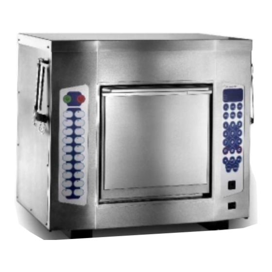
- Page 1 Evolution S E R V I C E M A N U A L For all Evolution models manufactured from January 2001 Part No. 32Z3382e Issue No. 3 CAUTION MICROWAVE EMISSIONS DO NOT BECOME EXPOSED TO EMISSIONS FROM THE MICROWAVE...
-
Page 2: Table Of Contents
Circuit Diagram ..........21 & 22 Parts Matrix ............... 23 Reply Form ............... 24 Merrychef Limited, Station Road West, Ash Vale, Aldershot, Hampshire GU12 5XA,UK. Tel: +44 (0)1252 371000 Fax: +44 (0)1252 371007 Internet address: http://www.merrychef.co.uk E-mail: sales@merrychef.co.uk or service@merrychef.co.uk Page 2... -
Page 3: Safety Code
The On/Off switch on the oven is not adequate protection against electric shock, as it does not isolate all of the internal wiring from the mains. Upon completion of a service on a Evolution oven, or before reconnecting the appliance to the mains supply for testing, check all of the following points: •... -
Page 4: Product Specifications
PRODUCT SPECIFICATIONS Model Number: EV + Voltage + Frequency + Phase + Version Model prefix Voltage Frequency Phase Control Type 24=240V 5 = 50 Hz 1 = Single 6 = 60 Hz 2 = Twin 3= Three Phase Power Requirement Voltage Current Microwave Convection... -
Page 5: Dimensions. Location And Installation
DIMENSIONS AND LOCATION A sample of this product has been tested and found to be in conformity with the following directives: Directive Harmonised standards applied. EMC 89/336 EEC EN 55011 1991 (Emissions) EN 50082-1 1992 (Immunity) LVD 73/23 EEC EN 60 335-2-90 Page 5... - Page 6 INSTALLATION INSTRUCTIONS Power Supply Requirements The Evolution should be connected to a suitable electricity supply, which can cope with the switching-on surge that occurs with certain types of catering equipment, such as microwaves. Because of this requirement, we strongly recommend that a separate, suitably rated supply is installed for the oven.
-
Page 7: Manual Rhs Controls
MANUAL CONTROLS POWER PADS CONVECTION PAD TIME/PROGRAM SELECT PADS TEMPERATURE SETTING PADS CANCEL PAD PROGRAM PAD TIME AND PROGRAM DISPLAY MULTI-STAGE INDICATOR COLON 10 ON/OFF SWITCH 11 ERROR DISPLAY PHUU\FKHI 7 TIME P R O G R A M DISPLAY POWER PADS CANCEL/ CALLBACK ‘C’... -
Page 8: Error Codes And Diagnostics
Error Codes and Diagnostics The Evolution will identify some of the most common problems by flashing an error message code in the time display window. (See also Error Light Operation page 17). These are the error messages and suggestions for repairing them. -
Page 9: Main Features
These are part of the ventilation system and of damage. At the first sign of wear they should be must be kept free of obstruction and cleaned on a replaced by a Merrychef approved engineer. daily basis. Page 9... -
Page 10: A -Power Output Testing To En 60335-2-90:1996
Procedure A - Power Output Test in accordance with BS EN 60335-2-25:1996 Annex AA This test is given in the BSI test standard for microwave ovens. It is reproduced below - not so that you can follow it, but to show you why it is impractical in normal conditions. A simplified procedure, which gives a good approximation to the BSI power output, is given in Procedure B which follows. -
Page 11: B - Power Output Testing
Procedure B - Simplified Power Test You will need: A thermometer capable of reading to ±0.1°C. A Polypropylene tray approximately 200 mm x 200 mm. A measuring jug. A calculator. Water which is at a temperature of 10°C ± 2°C. 1. -
Page 12: D - High Voltage Capacitor Test
Procedure D - High Voltage Capacitor Test You will need: A Digital Multi-meter (D.M.M.) A Megger or similar resistance meter using 500V d.c. WARNING: High voltages and large currents are present at the High Voltage Capacitor. It is very dangerous to work near this part when the oven is on. NEVER make any voltage measurements at the High Voltage circuits, including the magnetron filament . -
Page 13: Principal Components: Right Side View
PRINCIPAL COMPONENTS Right side Shown with component module cover removed Magnetron cooling fan 310110 9A Fuse 3 Amp 30Z0940 9B Fuse Holder 30Z0231 Magnetron 30Z0851 10A Fuse 1 Amp 30Z0957 2A Self Tap Screw 31Z3133 10B Fuse Holder 30Z0231 Hot air fan 30Z1131 11A Fuse 10 Amp 30Z0217... -
Page 14: Principal Components: Right Side View
Left side 17A Fuse 1 Amp 30Z0957 17B Fuse Holder 30Z0231 18A Fuse 1 Amp 30Z0957 18B Fuse Holder 30Z0231 19A Fuse 10 Amp 30Z0217 19B Fuse Holder 30Z0957 Page 14... -
Page 15: Principal Components: Rear View, Top View
Rear view 20A 20B 22A 22B 24A 24B Top view 20A Fuse 13 Amp 30Z0168 23 Interlock Contactor 340504 20B Fuse Holder 30Z0231 24A Fuse 25 Amp 31Z0473 21 Turntable motor RMC5055EX 24B Fuse Holder 31Z0474 22A Fuse 13 Amp 30Z0168 25 Heater Contactor 340504... -
Page 16: Oven Door Assembly
OVEN DOOR ASSEMBLY Black Handle RBR12852 Door Frame 40H0158 Door Cover Outer Skin 40H0080 Insulation Panel 40H0081 Door Reinforcement RMC70722 Striker Pin 31Z1214 Door Frame (B) MC3055 Insulation Wrap 32Z0001 Window Screen 40H0082 Door Base Silver MC3031KX04 Door Cover MC3064 Plate - Door Switch MC3056 Packing (B) -
Page 17: Door Interlock Operation
Door Interlock Operation The door on the Evolution oven is monitored by four microswitches. Three of these are used in the conventional “Primary, Secondary and Monitor” switch arrangement shown below, while the fourth is a low-voltage switch linked directly to the control circuitry. -
Page 18: Input Wiring Details
INPUT WIRING DETAILS 2-Phase, Neutral and Earth Green / Yellow Blue Black Brown Single Phase Green / Yellow Blue Brown Note: early models are fitted with a 3-way terminal block Mains Terminal Block 31Z0477 Cable Gland 31Z1070 48A Gland Nut 31Z1082 Mains Cable 4 Core 31Z0480... -
Page 19: Control Panel Assembly
Control Panel Assembly Membrane Assembly 11H0048 On/Off Switch 30Z0503 Logic Assembly 11H0045 Support Shield 40H0075 Relay (PCB) Board 11H0046 15 Way Ribbon Connector 11Z0298 Models with Serial No.s prefix ‘PEV____’ only 43A Logic Assembly 11H0042 45A Relay (PCB) Board 11H0043 Page 19... -
Page 20: Membrane Panel Circuit
Membrane Panel Circuit You will need: A Digital Multi-meter (D.M.M.) Isolate the oven from the mains supply. Remove the Logic Assembly from the Control Panel Housing. Unplug the membrane “tail” from the Logic PCB Assy. Using a D.M.M., check for continuity between the correct terminals when the pads are pressed. -
Page 21: Circuit Diagram
Circuit Diagram: Part 1 Page 21... -
Page 22: Circuit Diagram
Circuit Diagram: Part 2 Page 22... -
Page 23: Parts Matrix
Parts Matrix Magnetron cooling fan 310110 Heater Contactor 340504 Overheat Safety Stat 30Z1024 Magnetron 2M121 30Z0851 Black Handle RBR12852 2A Self Tap Screw 31Z3133 Door Frame 40H0158 Hot air fan 30Z1131 Door Cover Outer Skin 40H0080 Transformer 30Z0931 Insulation Panel 40H0081 Axial fan 30Z0941... -
Page 24: Reply Form
Name Address Page on which error occurs (if applicable) - Evolution: Description of error Suggestion for improvement to manual Please return this form to:...
Need help?
Do you have a question about the Evolution and is the answer not in the manual?
Questions and answers