Table of Contents
Advertisement
Quick Links
Advertisement
Table of Contents

Subscribe to Our Youtube Channel
Related Manuals for Merrychef eikon e2


Summary of Contents for Merrychef eikon e2
- Page 1 eikon Service & Parts Manual eikon CAUTION MICROWAVE EMISSIONS: DO NOT BECOME EXPOSED TO EMISSIONS FROM THE MICROWAVE GENERATOR OR PARTS CONDUCTING MICROWAVE ENERGY. Service & Parts Manual original Instructions Part Number 32Z3839 GB Issue 5...
- Page 2 SYMBOLS The symbols below are used, where applicable, as visual guidance throughout this manual. DANGER This symbol is shown if there is a high risk of severe personal physical injury. The relevant safety precautions MUST be observed and implemented at all times. WARNING This symbol is shown if there is a possible risk of personal physical injury or if damage may occur to the equipment.
-
Page 3: Table Of Contents
CONTENTS SAFETY & REGULATIONS 15.3 ERROR LOG 15.4 OVEN COUNTERS 1 SAFETY REQUIREMENTS 15.5 VISUAL VIEW 1.1 Important: 16 FIRMWARE UPDATES PRODUCT DETAILS TESTING COMPONENTS 2 PRODUCT OVERVIEW & FUNCTIONS 17 OVEN TESTING 3 MAIN FEATURES 17.1 Equipment required 4 TECHNICAL SPECIFICATIONS 17.2 Earth/Insulation Test: 4.1 Specifications 17.3 Screen calibration:... -
Page 4: Safety Requirements
SWITCH OFF THE OVEN - DISCONNECT/ISOLATE who have successfully undertaken a recognised product FROM THE ELECTRICAL SUPPLY - familiarisation and training course run by Merrychef to carry kEEP THE OVEN DOOR CLOSED TO STIFLE ANY out service/repair tasks to the appliance/s shown on the FLAMES. -
Page 5: Product Overview & Functions
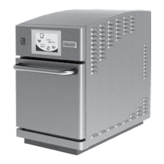
2 PRODUCT OVERVIEW & FUNCTIONS CONSTRUCTION Stainless steel cavity and casework. CONTROL SYSTEM Colour touchscreen, icon driven. Storage for up to 1024 programs with 6 stages per cooking program providing a user instruction for each stage. USB memory stick data transfer. MICROWAVE POWER Distribution system, rotating active antennae. -
Page 6: Main Features
These ensure a tight seal around the door. They should be kept clean and checked regularly for signs of damage. At the first sign of wear they should be replaced by a Merrychef approved Service Agent. 10 CRUMB FILTERS, IMPINGER PLATE & COOK PLATE The metal crumb filters covering the convection paths in the oven cavity sides must be kept clean and free of debris. -
Page 7: Technical Specifications
4 TECHNICAL SPECIFICATIONS 4.1 Specifications Description unit Touch screen controls programs 1024 Ambient operating temperature °C/°F <40/104 External HxWxD 633x383x785 External HxWxD inches 25x15x31 Internal HxWxD 244x244x305 Internal HxWxD inches 9.6x9.6x12 Cooking chamber Ltr (cu.ins) 19.4 (1175) Power output microwave Watts 1000 Power output convection... - Page 8 Sheffield. GU3 1LR S35 9ZX Equipment details Generic Model Numbers eikon e2 Description Commercial Combination Microwave Oven Declaration of Conformity with directives and standards The manufacturer hereby declares that its commercial combination microwave ovens listed above comply with the following directives and standards.
-
Page 9: Installation
6 INSTALLATION 6.1 OVEN LOCATION AND POSITIONING Choose a site away from major heat sources. DO NOT position so that hot air is drawn in from fryers, grills, griddles, etc. A heat barrier to the height of the oven must be installed if sited next to a burner, stove or range. -
Page 10: Electrical Installation
7 ELECTRICAL INSTALLATION DANGER! THIS APPLIANCE MUST BE EARTHED. FAILURE TO DO SO MAY RESULT IN ELECTRIC SHOCk AND DEATH. The oven must be connected to a separate electrical supply installed by a qualified and approved electrician. A suitably rated isolating switch with a 3mm contact gap on all poles should be fitted for each oven installed. -
Page 11: Electrical Installation Guide
8 ELECTRICAL INSTALLATION GUIDE DANGER! WARNING THIS APPLIANCE MUST BE EARTHED. FAILURE HIGH LEAkAGE CURRENT. TO DO SO MAY RESULT IN ELECTRIC SHOCk AND DEATH. EQUIPOTENTIAL The oven must be connected to a separate An Equipotential Earth point is provided on electrical supply installed by a qualified and the rear panel of the oven for independent approved electrician. -
Page 12: Quick Start Guide: Quick Service Oven
9 QUICk START GUIDE: QUICk SERVICE OVEN The easyToUCH screen display, layout and icons shown herein, are for guidance purposes only and are not intended to be an exact representation of those supplied with the oven. 9.1 START UP 1. Switch the oven on; Make all the relevant safety checks and ensure the oven is clean and empty before pressing the oven switch down to activate the oven. -
Page 13: Using A Cooking Program
9.2 USING A COOkING PROGRAM Taking all the necessary precautions to ensure you do not burn yourself, open the oven door to place the food into the hot oven and close the door. 1. Select a program group, for example, ‘BURGERS’ to display the individual cooking programs. -
Page 14: Operating Guide: Full Service Oven
10 OPERATING GUIDE: FULL SERVICE OVEN 10.1 easyToUCH MAIN MENU & kEYBOARD SCREEN MAIN MENU SCREEN: 1. DEVELOPMENT MODE enables multistage cooking programs to be developed, then stored under a name and symbol for reuse. This also enables the DEVELOPMENT use of the oven in a manual mode of operation. -
Page 15: Development Mode: Creating Acook Program
10.2 DEVELOPMENT MODE: CREATING A COOk PROGRAM 1. Select the ‘chef’s hat’ symbol from the main menu to enter development mode. Enter stage 1 of the program 2. The temperature displays the set preheated oven temperature. To increase or decrease the temperature required, select the temperature symbol (2), enter the Example below;... -
Page 16: Press & Go
10.3 PRESS & GO Running a cooking program from the Press & Go menu. 1. Select ‘PRESS & GO’ from the main menu screen. 2. Select the item required to cook. 3. The display shows the cooking time count down. The timer bar turns red to indicate the cooking cycle has finished. -
Page 17: Changing The Oven Temperature
4. Select the required cooking program to start cooking. For example, ‘1 BURGER’ . 5. The program either starts immediately displaying a countdown timer, or an instruction is displayed first; follow the stage instruction then select OK to start cooking. If the oven door is not opened within 30 seconds a warning message appears. -
Page 18: Adding A New Program Group
10.7 ADDING A NEW PROGRAM GROUP To add a new Program Group. 1. Select ‘COOKBOOK’ from the main menu screen. 2. Select ‘EDIT COOKBOOK’ . 3. Select the ‘ADD A NEW GROUP’ symbol. 4. Select the camera icon to open pictures. 5. -
Page 19: Adding A Program To A Group
10.9 ADDING A PROGRAM TO A GROUP To add a cooking program to an existing PROGRAM GROUP. Example add Program ‘4 BURGERS’ to the program group ‘BURGERS’ . 1. Select ‘COOKBOOK’ from the main menu screen. 2. Select the ‘BURGERS’ Program Group. 3. -
Page 20: Oven Control Settings
11 OVEN CONTROL SETTINGS 1. Select the ‘settings’ symbol from the main menu screen. 2. Enter the password and select OK to display the Settings menu (3) comprising: A. Oven mode/navigation settings. B. Language options. C. Oven temperature settings and labels. D. -
Page 21: Recipe Counters (E)
11.4 Recipe counters (E) 11.4.1 Select the clipboard symbol to display a listing of recipe counters. 11.4.2 If shown, use the arrows (bottom right) to scroll up and down the list. 11.5 Date and Time settings (F) 11.5.1 Select the time/date symbol to display the setting options. -
Page 22: Usb Oven Programs (J)
(1 ‘.cbr’ + ‘autoupd.ate’). 11.8.1 With the oven switched off, slide the Merrychef badge (oven front top right) upwards and insert the USB Memory Stick into the slot. 11.8.2 Switch the oven ON. -
Page 23: Cooling The Oven Down Before Cleaning
12 COOLING THE OVEN DOWN BEFORE CLEANING 12.1 Oven cool down IMPORTANT: the oven must be cooled down before the cleaning processes are carried out. 1. In Full Serve mode, select the CLEANING symbol from the main menu. 2. In Full or Quick Serve mode, select the blue thermometer symbol to disable heating and start the cooling cycle. -
Page 24: Cold Oven Cleaning Instructions E2
13 Cold oven CLEANING INSTRUCTIONS e2 Complete COOL DOWN procedure and allow the oven and accessories to cool before commencing cleaning. DO NOT USE TOOLS REMOVE & CLEAN Oven Parts: 1. Remove the air filter at the rear of the oven by sliding upwards. -
Page 25: Servicing The Oven
14 SERVICING THE OVEN 14.1 Servicing Procedure: DANGER: 14.1.1 Disconnect/isolate the oven from the power BEFORE REMOVING THE OVEN CASING, ISOLATE THE supply. OVEN FROM THE MAINS ELECTRICITY POWER SUPPLY; SWITCH OFF, DISCONNECT OVEN PLUG FROM WALL 14.1.2 Check the oven is correctly installed as SOCkET, TURN OFF ISOLATOR SWITCH TO DISCONNECT described in the Installation Instructions (Product FIXED WIRED OVENS AND LOCk-OFF. -
Page 26: Errors & Diagnostics
15 ERRORS & DIAGNOSTICS 15.1 ERROR MESSAGES 15.1.1 A description of the type of error is shown. Check for a number following ‘ERROR:’ (A) and refer to the Error Codes (Fault Finding section) for more details. The Oven Serial Number, Model, UI (QTS) version and SRB version information is also displayed below. -
Page 27: Visual View
15.5 VISUAL VIEW 15.5.1 Select VISUAL VIEW (E) to check the main oven components. Select a component symbol to switch on (red), select again to increase the level or turn off (green). 15.5.2 Open the oven door and check the colour changes from green to red on the display to check the door microswitch/interlock circuit is operating. -
Page 28: Firmware Updates
16 FIRMWARE UPDATES 16.1 Note: if icons are not displayed on the screen, press in the same positions on screen as the missing icons to select. 16.1.1 Switch on the oven. 16.1.2 Tap the top right of the screen (1) or the same position if it is not displayed to bypass oven preheat. -
Page 29: Srb Firmware Update
16.1.9 Enter the password and select OK to display the Settings menu, see (2). 16.1.10 Select the USB symbol (4). 16.1.11 Slide the Merrychef badge (oven front top right) upwards and insert the USB Memory Stick into the slot (3). - Page 30 For update A) follow all instructions: For update B) follow the first 2 instructions: 16.1.24 With the oven switched off, slide the Merrychef badge (oven front top right) upwards and insert the USB Memory Stick into the slot (1). 16.1.25 Switch the oven ON (2).
-
Page 31: Oven Testing
17 OVEN TESTING 17.1 Equipment required DANGER: ● Portable Appliance Tester (P.A.T.). BEFORE REMOVING THE OVEN CASING, ISOLATE THE OVEN FROM THE MAINS ELECTRICITY POWER SUPPLY; ● Digital Multi-meter (D.M.M.). SWITCH OFF, DISCONNECT OVEN PLUG FROM WALL ● Megger / similar 500V d.c. resistance meter. SOCkET, TURN OFF ISOLATOR SWITCH TO DISCONNECT ●... -
Page 32: Oven Tests
17.4 OVEN TESTS 17.4.1 Enter Service mode (Servicing section). 17.4.2 Select the down arrow to display the individual Oven tests (A) for the oven to perform. 17.5 Microwave Power Test Measuring the power output. Note: The power output is established under IEC 705 standard method which is only workable in Laboratory controlled conditions. -
Page 33: Microwave Leakage Test
17.6.8 Readings must be below 5mW/cm². If a level greater than 5mW/cm² is observed, this should be reported to the Merrychef Service Department immediately, and the oven should not be used. 17.6.9 Notes should be kept of any leakage that is observed in terms of the level and position on the oven. -
Page 34: Temperature Control Test
17.7 Temperature Control Test Measuring the oven cavity temperature. (Note; re-calibrating the Thermocouple with the SRB is normally only required when the Thermocouple has been replaced or the oven is under or over cooking.) Procedure: 17.7.1 Place the probe of a temperature reader (A) onto a heat sink in the centre of the oven cavity and close the oven door. -
Page 35: Soak Test
17.8 Soak Test Checking the oven cavity integrity. Procedure: 17.8.1 Place an oven/microwave safe container with approx. 2 litres of water into the oven. 17.8.2 Close the oven door and select ‘Soak Test’ (A) from the Service mode oven tests (maximum oven temperature, 50% microwave power, maximum fan speed). -
Page 36: High Voltage Components
18 HIGH VOLTAGE COMPONENTS High voltages and large currents are present at DANGER: the High Voltage Capacitor. It is very dangerous BEFORE REMOVING THE OVEN CASING, ISOLATE THE to work near this part when the oven is on. OVEN FROM THE MAINS ELECTRICITY POWER SUPPLY; NEVER make any voltage measurements at the SWITCH OFF, DISCONNECT OVEN PLUG FROM WALL High Voltage circuits, including the magnetron... -
Page 37: High Voltage Capacitor Test
High voltages and large currents are present at the High Voltage Capacitor. It is very dangerous to work near this part when the oven is on. NEVER make any voltage measurements at the High Voltage circuits, including the magnetron filament. 18.3 High Voltage Capacitor Test 18.3.1 Disconnect and isolate the oven from the electricity supply. -
Page 38: Mains Voltage Components
19 MAINS VOLTAGE COMPONENTS 19.1 Door Interlock Adjustment Located on the door hinges are 3 safety interlock microswitches, to prevent microwave emissions escaping when the oven door is opened: The Primary (SW3) breaks the electrical supply circuit to the transformers. The Secondary (SW2) breaks the microwave circuit if the primary fails. -
Page 39: Convection Fan Motor & Controller
19.2 Convection Fan Motor & Controller 19.2.1 Convection Fan Motor. The convection motor is a 3-phase AC motor having a maximum speed of 3500 rpm controlled by a motor speed controller. The windings are thermally protected. 19.2.2 Motor Controller Provides a 3-phase AC switched mode drive to the convection motor and is controlled by a 0 - 10 Volt signal from the SRB. -
Page 40: Oven Components
20 OVEN COMPONENTS DANGER: BEFORE REMOVING THE OVEN CASING, ISOLATE THE OVEN FROM THE MAINS ELECTRICITY POWER SUPPLY; SWITCH OFF, DISCONNECT OVEN PLUG FROM WALL SOCkET, TURN OFF ISOLATOR SWITCH TO DISCONNECT FIXED WIRED OVENS AND LOCk-OFF. WARNING: ALLOW OVEN TO COOL. OBSERVE AND FOLLOW ALL SAFETY PRECAUTIONS INCLUDING THOSE DESCRIBED UNDER THE SAFETY REGULATIONS SECTION OF... - Page 41 11 Overheat stat Magnetron 12 Microswitch SW3 13 Oven door 14 LH Door hinge assembly 15 Temperature sensors (2 x parallel Thermocouples) oven cavity 16 Fuse (20A) 17 Neutral cut-out relay (Omron 12v DC Relay)18 HT Transformer (10A) 19 Control circuit Fuse (7A) 20 Smart Relay Board (SRB) 21 Heater element switching relay (240V) 22 Stirrer...
-
Page 42: Srb & Qts Circuit Boards
21 SRB & QTS Circuit Boards 21.1 SRB replacement 21.1.1 Disconnect and isolate the oven from the electricity supply. 21.1.2 Allow the oven to cool down. 21.1.3 Remove the oven top panel. 21.1.4 Ensure that the High Voltage Capacitor is discharged before commencing work. -
Page 43: Pm (Personality Module) Replacement
21.3.3 Enter the service password and select OK to display the Settings menu, see (3). 21.3.4 Select the USB symbol (4). 21.3.5 Slide the Merrychef badge upwards and insert the USB Memory Stick into the slot (5). 21.3.6 Once the USB has stopped flashing, select the required USB recipe symbol (6). -
Page 44: Spare Parts Exploded View
22 SPARE PARTS EXPLODED VIEW Service & Parts Manual original Instructions Part Number 32Z3839 GB Issue 5... - Page 45 CATALYST DJ0081 e2 HEATER ELEMENT DJ0084 DOOR FRAME INSULATION DJ0085 CHOKE INSUATION DJ0100 e2 BASE SEAL DR0009 MERRYCHEF BADGE GUIDE DR0011 TOUCH SCREEN OVERLAY DR0021 HARMONISED SPEAKER 30Z1427 OVERHEAT Cav STAT SMALL DR0045 SPEAKER WIRE DR0049 MERRYCHEF BADGE SMALL Service &...
-
Page 46: Spare Parts
Description Unit To Go Box BOM No. Number Ovens Ovens kit # Oven Ovens DR0050 MERRYCHEF BADGE SEAL SM DR0051 MERRYCHEF BADGE SLIDER SM DV0370 LOWER IMPINGER HANDLE DV0431 DOOR HANDLE DV0552 GEAR - STIRRER WHEEL P11M0339 MAINS CABLE ASSEMBLY... -
Page 47: Error Codes Displayed
25 ERROR CODES DISPLAYED Error Error System Error Condition Description Trigger Possible Causes Code Level Response Supply Voltage Error (+/- 10% of rated voltage) Re-commission test Warning Cooling Test Fail User input error message message Convection Test Re-commission test Warning User input Fail error message... - Page 48 Error Error System Error Condition Description Trigger Possible Causes Code Level Response The current measured by the Failure of Display error Detects a magnetron Magnetron failed current sensing component/s in message until E 101 is not working Critical to energise transformer the microwave system is...
- Page 49 Error Error System Error Condition Description Trigger Possible Causes Code Level Response The BTS or SRB The PM has been either has an Display error changed and is Wrong PM found / no incorrect PM message until E 109 SRB PM error incorrect.
-
Page 50: Srb & Qts Circuit Boards
26 SRB & QTS Circuit Boards 26.1 QTS LEDs ● Run - Pulsing 1 second flash, indicating that the board has booted up. ● Power - Lit to show that there is a power supply from the SRB. ● P-Bus - Irregular flashing, indicating data communication with SRB. -
Page 51: Srb Led's
26.3 SRB LED’s ● P-Bus - Irregular flashing, indicating data communication with BTS. ● Run - Pulsing 1 second flash, indicating that the board has booted up. ● 12v & 5v - Lit to show voltage outputs from inboard transformer. ●... -
Page 52: Srb Terminal Locations
26.4 SRB Terminal Locations: 1 X3 - Output for e2 convection motor controller. 2 X101 - Voltage Selection Relay coil feeds. 3 X18b - NOT USED - Bridged with Jumper. 4 X18e - Neutral cutout relay and link. 5 X18d - Magnetron overheat thermostat. 6 X18c - Cavity Overheat Thermostat. - Page 53 Service & Parts Manual original Instructions Part Number 32Z3839 GB Issue 5...
-
Page 54: Circuit Diagrams
27 CIRCUIT DIAGRAMS 50Hz 13A Service & Parts Manual original Instructions Part Number 32Z3839 GB Issue 5... - Page 55 Service & Parts Manual original Instructions Part Number 32Z3839 GB Issue 5...
- Page 56 28 CIRCUIT DIAGRAMS 50Hz 16A Service & Parts Manual original Instructions Part Number 32Z3839 GB Issue 5...
-
Page 57: Control Circuit
Service & Parts Manual original Instructions Part Number 32Z3839 GB Issue 5... -
Page 58: Heater Circuit E2 13A
29 CIRCUIT DIAGRAMS 50Hz 20A Service & Parts Manual original Instructions Part Number 32Z3839 GB Issue 5... -
Page 59: Heater Circuit E2 15A
Service & Parts Manual original Instructions Part Number 32Z3839 GB Issue 5... -
Page 60: Heater Circuit E2 20A
30 Commissioning the oven 30.1 Initial installation 28.1 After Service 1 Unpack the Oven and check for damage. Complete the following checks after the Oven has been Serviced/Repaired/Tested before connecting to the 2 Check Oven Accessories. mains electricity power supply: 3 Check location will provide adequate Ventilation. -
Page 61: Microwave Circuit E2 13/15A
Fa x: +44(0)1483 464905 w w w.manitowo c fo o d ser vi ce.com Merrychef reserves the right to change product specifications without notice and accepts no liability for any inaccuracies, errors or ommissions contained herein. Service & Parts Manual original Instructions...
Need help?
Do you have a question about the eikon e2 and is the answer not in the manual?
Questions and answers