Table of Contents
Advertisement
Quick Links
Version 3.0
Version 2.0
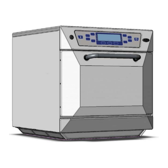
EC402s
US Models including WAWA
S E R V I C E & P A R T S M A N U A L
This manual covers US models manufactured from:
ISSUE 5
Version 2.0 Serial No. 000745 –001199
23.02.2008
Version 3.0 Serial No. 001200 onwards
CAUTION MICROWAVE EMISSIONS
DO NOT BECOME EXPOSED TO EMISSIONS FROM THE MICROWAVE
GENERATOR OR PARTS CONDUCTING MICROWAVE ENERGY
402s Ovens Pt. No. 32Z3522 Issue 5
1
Advertisement
Table of Contents

Related Manuals for Merrychef EC402s


Summary of Contents for Merrychef EC402s
- Page 1 Version 3.0 Version 2.0 EC402s US Models including WAWA S E R V I C E & P A R T S M A N U A L This manual covers US models manufactured from: ISSUE 5 Version 2.0 Serial No. 000745 –001199 23.02.2008...
-
Page 2: Table Of Contents
Appendix 2: MenuKey Procedures ........36-37 Appendix 3: Cleaning Procedure ........38-40 Appendix 4: Recommended Spares List .......41 Appendix 5: PCB connection Points ........ 42-43 Appendix 6: Engineering Test Settings........44 Merrychef USA 1111 North Hadley RD Fort Wayne IN 46804 Phone: 877/404 - 6872 Fax: 800/285 - 9511 e-mail: info@merrychefusa.com... -
Page 3: Microwave Safety Precautions
MICROWAVE SAFETY PRECAUTIONS CAUTION WARNING TO SERVICE TECHNICIANS PRECAUTIONS TO BE OBSERVED BEFORE AND DURING SERVICING TO AVOID POSSIBLE EXPOSURE TO EXCESSIVE MICROWAVE ENERGY (a) Do not operate or allow the oven to be operated with the door open. (b) Make the following safety checks on all ovens to be serviced before activating the magnetron or other microwave source, and make repairs as necessary: 1) interlock operation. -
Page 4: Safety Code
SAFETY CODE This manual is designed to assist engineers who have been on a recognised product familiarisation and training course run by Merrychef. It has been prepared to offer technical guidance for the 402s range of Ovens. Please remember that it is wiser not to attempt a service task if you are unsure of being able to complete it competently, quickly, and above all safely. -
Page 5: Product Specifications
PRODUCT SPECIFICATIONS Model Number: 402S VVV F P C R TT ZZ Example 402S2086DK3GMUS Model No. EC402s 208V, 60Hz, 2P + GND supply, MenuKey Revision 3, General Market, USA Supply Freq. Control Country Phase/Supply Type Voltage Type /Region Voltage (ac) -
Page 6: Installation Instructions
INSTALLATION INSTRUCTIONS Installation Instructions for Mealstream Combination Ovens Power Supply Requirements The Mealstream Series should be connected to a suitable electricity supply, which can cope with the switching-on surge that occurs with certain types of catering equipment, including microwaves. Because of this requirement, we strongly recommend that a separate, suitably rated supply is installed for the oven. -
Page 7: Main Features
MAIN FEATURES a On/Off SWITCH h DOOR This is used to turn the oven On or Off. The door consists of a thermally insulated inner section, and an additional air gap provided by a IT DOES NOT ISOLATE INTERNAL WIRING twin skinned door front to lower the surface FROM THE MAINS SUPPLY. -
Page 8: Electronic Control Panel
MAIN FEATURES Electronic control panel Version 2.0 MAIN DISPLAY START PANEL FAN SPEED PADS MenuKey PREHEAT/ COOL DOWN PROGRAM POWER PADS FUNCTION CANCEL TIME/ PROGRAM PADS PADS CANCEL PAD MenuKey Cancels all timed cooking cycles, pre-programmed The MenuKey System automatically changes all the operations and stops the microwave energy. - Page 9 MAIN FEATURES Electronic control panel Version 3.0 MAIN DISPLAY PANEL MenuKey COOL DOWN FUNCTION FUNCTION FUNCTION CANCEL PADS PADS PADS MenuKey 2 DISPLAY PANEL The MenuKey System automatically changes all the Shows the principal functions of the oven. cooking programs with an electronic key and allows When cooking, the time remaining counts down.
-
Page 10: Principal Components: Rhs
PRINCIPAL COMPONENTS: Right Side Description Part No. Cavity High limit Stat 30Z1024 Motor Start Capacitor 2µF ( Blue ) 30Z1298 Filter 16A 30Z1339 Air filter SA276 Stirrer motor Assembly SA238 Stirrer (inside cavity) SA213 Microswitch SW1 30Z1294 Microswitch SW2 Door Hinge Assembly RH SA202 Magnetron Cooling Fan 30Z1295... -
Page 11: Principal Components: Lhs
PRINCIPAL COMPONENTS: Left Side Description Part No. Filter 16A 30Z1339 Air filter SA302 Stirrer motor Assembly SA238 Stirrer (inside cavity) SA213 Microswitch SW3 30Z1294 Microswitch SW4 Door Hinge Assembly LH SA203 Motor Controller 30Z1293 HV Capacitor 2500V 0.88μF ( 60Hz models ) 30Z1251 25A HV Capacitor clip (0.88μF) 88mm 31Z0521... -
Page 12: Principal Components: Top
PRINCIPAL COMPONENTS: Control Box Principal components: POWER SUPPLY Description Part No. Fuse 10A HRC 30Z0217 Gold resistor ( 220R ) 30Z0235 Relay PCB Assembly 11K0004 Ribbon Cable 15way 11Z0298 Ribbon Cable 10way MenuKey 11M0117 Logic PCB Assembly Version 2.0 SA231 Logic PCB Assembly Version 3.0 SA260 Transformer LT (Low voltage) -
Page 13: Principal Components: Back View
PRINCIPAL COMPONENTS: Back view Description Part No. Cable Gland 31Z0500 Cable Gland Nut 31Z0499 DV0576 Heater Element 208V 650W DV0606 Heater Element 220V 650W Heater Element 240V 650W DV0607 Magnetron 30Z1171 Magnetron Thermistor Assembly SA234 Convection ( Hot Air ) Motor Assembly SA208 Thermistor Cavity 30Z1315... -
Page 14: Principal Components: Power Supply
PRINCIPAL COMPONENTS: Power Supply Description Part No. Filter 16A 30Z1339 Fuse 10A HRC 30Z0217 Cable Gland 31Z0500 Cable Gland Nut 31Z0499 Electrical Supply Lead Assembly SA217 Terminal Block 31Z0447 Fuse 20A FLM 30Z1177 Fuse Holder 30A 30Z1178 Fuse Holder 10A 30Z0231 402s Ovens Pt. -
Page 15: Principal Components Cavity Parts
PRINCIPAL COMPONENTS Cavity parts Description Part No. Grease Filter ( 2 parts ) SA340 SA339 Stirrer Glass DV0492 Rack Support ( Not shown ) DV0114 Upper Impinger plate SA211 Rack DV0275 Lower Impinger plate SA266 * Parts 35 & 37 Contact Service Department KFC Accessories 65 Chicken Griddle SA133 Description... -
Page 16: Principal Components: External Panels
PRINCIPAL COMPONENTS External Parts Control Panel See page 15 Door Assembly Description Part No. Air Filter SA276 Top Trim DV0187 Rear Panel SA329 Side Panel LH DV0091 Door Skin DV0501 Door Handle 32Z1066 Door Inner SA331 Door Choke DV0168 Door Seal DV0305 Bottom Trim DV0037... -
Page 17: Principal Components: Control Panel
PRINCIPAL COMPONENTS Electronic Control Panel Assembly Version 2.0 Version 3.0 *Note: On Ovens with Serial No.s before 000745 ( WAWA Models) External Panels Item 51 is only available to special order. Description Part No. MenuKey Dust Cover DV0052 Power switch (On/Off) 30Z1318 GM Membrane Version 2.0 DV0055... -
Page 18: Parts Matrix
Part number identification chart 1 Ref. No. Description Part No. Cavity High limit Stat 30Z1024 Motor Start Capacitor 2µF ( Blue ) 30Z1298 Filter 16A 30Z1339 Air filter SA276 Stirrer motor Assembly SA238 Stirrer (inside cavity) SA213 Microswitch SW1, SW2, SW3, SW4 30Z1294 Door Hinge Assembly RH SA202... - Page 19 Part number identification chart 2 Ref. No. Description Part No. Fuse Holder 30A 30Z1178 Fuse Holder 10A 30Z0231 Grease Filter ( 2 parts ) SA339 SA340 Stirrer Glass DV0492 Rack Support DV0114 Upper Impinger plate SA211 Rack DV0275 Lower Impinger plate SA266 Top Trim DV0187...
-
Page 20: Procedure For Microwave Emission Test
Check for radiation emission after servicing. Should the emission be more than 4mW/cm² Inform Merrychef service centre immediately. After repairing or replacing any radiation safety device, keep a written record for future reference, as required by D.H.H.S. and Health and Welfare Canada regulation. - Page 21 • Readings must be below 4mW/cm². If a level greater that 4mW/cm² is observed, this should be reported to Merrychef Service Division immediately. • In any case, notes should be kept of the leakage that is observed. In terms of level and position on the oven.
-
Page 22: Procedure For Power Output Measurement
PROCEDURE FOR POWER OUTPUT MEASUREMENT The power output specification 1500W on this model is established under IEC 705 standard method. This method is only workable in Laboratory controlled conditions. An approximate method is as follows: Ensure the oven is cold before commencing the test Changing the Oven Profile In order to carry out the test the oven PREHEAT must be set to OFF[ V3.0 ] or 0ºF[ V2.0 ] to switch... -
Page 23: Procedures For Principal Component Tests
PROCEDURES FOR PRINCIPAL COMPONENTS TEST (1) 1. Power Transformer Test You will need: A Digital Multi-meter (D.M.M.) A Megger or similar resistance meter using 500V d.c. WARNING: High voltages and large currents are present at the High Voltage Capacitor. It is very dangerous to work near this part when the oven is on. -
Page 24: High Voltage Rectifier Test
PROCEDURES FOR PRINCIPAL COMPONENTS TEST (2) ( High Voltage Capacitor Test continued, ensure steps 1-4 on previous page have been completed) Between Terminals Pass if approximately 10 MΩ Between Terminals and Case Pass if open circuit 5. Using a Megger, test the insulation resistance between the terminals and the case. -
Page 25: Procedure For Door Interlock Adjustment
PROCEDURE FOR DOOR INTERLOCK ADJUSTMENT AND TEST 1 The door on the 402s oven is monitored by four microswitches. Three are used in the conventional “Primary, Secondary and Monitor” switch arrangement shown below and the fourth sends a signal to the Logic PCB. The switches operate as follows: Door Interlock Arrangement: Switches shown in Door Closed position Primary Secondary... -
Page 26: Electrical Supply
PROCEDURE FOR DOOR INTERLOCK ADJUSTMENT AND TEST 2 It is vital that the microswitches are adjusted to the correct position. There are two sets switch assemblies located either side of the oven. The interlocks ensure that the oven will not operate microwave with the door open. WARNING Before adjusting the microswitch assemblies ensure that the oven... -
Page 27: Hot Air Motor And Controller
PRINCIPAL COMPONENTS: Hot Air Motor & Controller 1 Convection and Fan Speed Control The convection heat is provided by 5 elements located in the hot box at the rear of the oven cavity. The hot air from the hot box passes over catalytic converters and is circulated into the bottom and top of the cavity through the impinger plates. - Page 28 PRINCIPAL COMPONENTS: Hot Air Motor & Controller 2 Motor Controller Provides an AC, 3-phase switched mode drive to the convection motor and is controlled by a 0 - 10 Volt signal from the logic board. This allows the motor to be adjusted from approximately 1500 rpm to 7000 rpm in steps of 5%.
-
Page 29: Wiring Diagrams
402s Ovens Pt. No. 32Z3522 Issue 5... -
Page 30: Trouble Shooting Guide
Trouble-Shooting Guide Is the problem Food Quality or Fundamental Operational Issue? Food Quality Fundamental Standard Food Quality Checks Standard Electrical Checks • Check that the PREHEAT temperature is • Check that oven is connected to an set correctly. Electricl Power supply and that any trip See User Manual. - Page 31 No Display Is Logic PCB Active ? See D7 LED Check cable from logic PCB to display is in place and no obvious wires are disconnected or shorted. Is Relay PCB Active see D27 Still Have a problem? Check 15 Way Ribbon Using spare display Cable between connect to Logic PCB...
- Page 32 5 Amps Check that the stirrer is rotating. Carry out Microwave Output Test Replace stirrer motor and retest Check Microwave Generating system Contact Merrychef Service Department for Further • Transformer assistance. • Magnetron • Capacitor • Diode 402s Ovens Pt. No. 32Z3522 Issue 5...
- Page 33 Cavity Sensor Error Report to Are there any Signs of Management and Cavity Fire Make Investigation Replace Sensor Check Temperature Retest and calibrate Sensor Resistance Oven. Re-Start Oven Activate Pre-heat Yes LED is on. Is Led D19 on relay PCB ON Check Heater Elements Replace if necessary...
- Page 34 Magnetron / Overheat issues Remove and Clean Air Filters. If Dirty—Advise operating staff of the need for this to be carried out on regular basis. See User Manual Still have a problem. Check Location of oven is away from any major heat sources.
-
Page 35: Appendix 1: Temperature Probe
APPENDIX 1: TEMPERATURE SENSOR RESISTANCE DATA Temperature Sensor Resistance Temp °F Temp °C Min. Rate Standard Max. Rate kΩ Rate kΩ kΩ 11.490 13.060 14.810 2.803 3.161 3.434 0.950 1.000 1.050 0.3572 0.3865 0.4171 R(200)°C = 1 kΩ ± 5% Note: These resistances will only be apparent in a stable cavity temperature as the sensor has a slow response time. -
Page 36: Appendix 2: Menukey Procedures
402s Ovens Pt. No. 32Z3522 Issue 5... - Page 37 402s Ovens Pt. No. 32Z3522 Issue 5...
-
Page 38: Appendix 3: Cleaning Procedure
APPENDIX 3: Cool Down Procedure To cool down and clean a hot oven Action EC402s V2.0 EC 402s V3.0 To commence Cool Down procedure Press Place Ice in cavity COOL DOWN MODE COOL DOWN MODE PLACE ICE IN CAVITY PLACE LOAD IN CAVITYAND... - Page 39 402s Ovens Pt. No. 32Z3522 Issue 5...
- Page 40 402s Ovens Pt. No. 32Z3522 Issue 5...
-
Page 41: Appendix 4: Recommended Spares List
APPENDIX 4: Recommended spares lists First Service 5-50 50-100 Piece Qty for Part No. Description Unit Aid Kit Ovens Ovens Ovens 600 Ovens 11H0010 HT DIODE ASSY 11K0004 RELAY PCB 11M0117 DC VOLTAGE CONNECTOR 10 WAY 11Z0298 15 WAY 0.1 RIBBON CABLE ASSY 30Z0217 FUSE 1in 10A HRC 30Z0231... -
Page 42: Appendix 5: Pcb Connection Points
APPENDIX 5: LOGIC PCB Connection Points and key features. Spare input not used Display Connecter Relay PCB 15 way Temp Calibration Connecter Door Switch IP Door switch Indicator ON when door closed Remote data point MenuKey Sockect Connector Program Motor speed D7 Power LED memory storage. - Page 43 APPENDIX 5: Relay PCB Connection Points and key features. D15 Magnetron active Cavity Temperature D16 Magnetron Sensor soft start Input D19 Heater ON Magentron Overheat sensor Inputs D20 LED when power is on Connector To when Microwave is Logic PCB operated.
-
Page 44: Appendix 6: Engineering Test Settings
402s Version 2.0/ 2.5 1. Switch the oven OFF 1. Switch the oven OFF 2. Switch ON and immediately press Edit Preheat 2. Switch ON and Temp. immediately press merrychef Edit Preheat to show the ENTER Edit Preheat Profile PREHEAT TEMP screen.
Need help?
Do you have a question about the EC402s and is the answer not in the manual?
Questions and answers