Merrychef eikon e2 Service & Parts Manual
Hide thumbs
Also See for eikon e2:
- Quick start manual (25 pages) ,
- Installation and user manual (28 pages)
Table of Contents
Advertisement
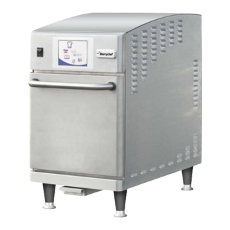
eikon e2
Service & Parts Manual
NOTE: PLEASE READ COMPLETELY
BEFORE ATTEMPTING TO INSTALL,
OPERATE OR SERVICE THIS EQUIPMENT
CAUTION MICROWAVE EMISSIONS:
DO NOT BECOME EXPOSED TO EMISSIONS
FROM THE MICROWAVE GENERATOR OR
PARTS CONDUCTING MICROWAVE
ENERGY.
Merrychef USA, LLC
1111 North Hadley Road
Fort Wayne, Indiana 46804
United States of America
Technical Support Hotline: (800) 678-9511
Telephone: (260) 459-8200
www.merrychefusa.com
Advertisement
Table of Contents

Subscribe to Our Youtube Channel
Related Manuals for Merrychef eikon e2


Summary of Contents for Merrychef eikon e2
- Page 1 eikon e2 Service & Parts Manual NOTE: PLEASE READ COMPLETELY BEFORE ATTEMPTING TO INSTALL, OPERATE OR SERVICE THIS EQUIPMENT Merrychef USA, LLC 1111 North Hadley Road CAUTION MICROWAVE EMISSIONS: Fort Wayne, Indiana 46804 DO NOT BECOME EXPOSED TO EMISSIONS...
-
Page 2: Table Of Contents
TABLE OF CONTENTS SYMBOLS .................................. 4 SAFETY REQUIREMENTS ............................5 PRODUCT OVERVIEW & FUNCTIONS ........................6 MAIN FEATURES ..............................7 TECHNICAL SPECIFICATIONS ..........................8 ............................... 8 PECIFICATIONS ): ..........................8 ERIAL UMBER ATING LATE OVEN PLACEMENT/INSTALLATION ........................9 INSPECT OVEN ..............................9 OVEN PLACEMENT .............................. - Page 3 ........................... 31 ICROWAVE EAKAGE ..........................32 EMPERATURE ONTROL ............................. 33 ECOMMISSION HIGH VOLTAGE COMPONENTS ..........................34 ..........................34 OWER RANSFORMER ) ..................... 34 OLTAGE ECTIFIER IODE OARD ..........................35 OLTAGE APACITOR .......................... 35 OLTAGE AGNETRON MAINS VOLTAGE COMPONENTS ......................... 36 ..........................
-
Page 4: Symbols
SYMBOLS The symbols below are used, where applicable, as visual guidance throughout this manual DANGER This symbol is shown if there is a high risk of severe personal physical injury. The relevant safety precautions MUST be observed and implemented at all times. ... -
Page 5: Safety Requirements
FROM THE ELECTRICAL SUPPLY - recognized product familiarization and training course KEEP THE OVEN DOOR CLOSED TO STIFLE ANY run by Merrychef to carry out service/repair tasks to FLAMES the appliance/s shown on the front cover of this... -
Page 6: Product Overview & Functions
PRODUCT OVERVIEW & FUNCTIONS CONSTRUCTION • Stainless Steel cavity and casework. CONTROL SYSTEM • Color touchscreen, icon driven. • Storage for up to 1024 programs with 6 stages per cooking program providing a user instruction for each stage. • USB memory stick data transfer. •... -
Page 7: Main Features
MAIN FEATURES ON/OFF SWITCH ON (I) activates the oven, OFF (0) switches the oven to standby mode. IT DOES NOT ISOLATE INTERNAL WIRING FROM THE MAINS SUPPLY. CONTROL PANEL Touch sensitive controls (easyToUCH) for controlling oven functions, including diagnostics and service mode. USB menuKey A socket, located under the logo, allows a USB menuKey to be used to update the cooking programs and oven... -
Page 8: Technical Specifications
TECHNICAL SPECIFICATIONS Specifications Eikon e2T (Twin) Eikon e2 Overall Size Overall Size Height (on 4” legs) 27" 686 mm Height (on 4” legs) 27" 686 mm Width 31.5” 800mm Width 14.75” 375 mm Depth (overall without handle) 28.5” 724 mm Depth (overall without handle) 28.5”... -
Page 9: Oven Placement/Installation
Upon receipt of this unit, immediately unpack and inspect for possible concealed shipping damage. If unit is found to be damaged, save all packing materials and contact your delivery carrier immediately. Failure to follow these instructions will negate Merrychef USA’s or your ability to file claims and receive compensation for shipping damage. ... -
Page 10: Electrical Installation
ELECTRICAL INSTALLATION DANGER! THIS APPLIANCE MUST BE EARTHED. FAILURE TO DO SO MAY RESULT IN ELECTRIC SHOCK AND DEATH. FOR ALL CORD CONNECTED APPLIANCES: GROUNDING INSTRUCTIONS This appliance must be grounded. In the event of an electrical short circuit, grounding reduces the risk of electric shock by providing an escape wire for the electric current. -
Page 11: Quick Start Guide: Quick Service Oven
QUICK START GUIDE: QUICK SERVICE OVEN The easyToUCH screen display, layout and icons shown herein, are for guidance purposes only and are not intended to be an exact representation of those supplied with the oven. START UP 1. Switch the oven on; Make all the relevant safety checks and ensure the oven is clean and empty before pressing the oven switch down to... -
Page 12: Using A Cooking Program
USING A COOKING PROGRAM WARNING: Taking all the necessary precautions to ensure you do not burn yourself, open the oven door to place the food into the hot oven and close the door. 1. Select a program group, for example, ‘BURGERS’... -
Page 13: Operating Guide: Full Service Oven
OPERATING GUIDE: FULL SERVICE OVEN easyToUCH MAIN MENU & KEYBOARD SCREEN 1. DEVELOPMENT MODE enables multistage cooking programs to be developed, then store under a name and symbol for reuse. DEVELOPMENT 2. PRESS & GO allows quick access to use the MODE cooking programs that are already stored. -
Page 14: Development Mode: Creating A Cook Program
DEVELOPMENT MODE: CREATING A COOK PROGRAM 1. Select the ‘chef’s hat’ symbol from the main menu to enter development mode. Enter stage 1 of the program 2. The temperature displays the set preheated oven temperature. To increase or decrease the temperature required, select the temperature symbol (2), enter the Example below;... -
Page 15: Press & Go
PRESS & GO Running a cooking program from the Press & Go menu: 1. Select ‘PRESS & GO’ from the main menu screen. 2. Select the item required to cook. 3. The display shows the temperature, cooking time, fan speed and microwave power while the timer counts down. -
Page 16: Changing The Oven Temperature
USING A COOKBOOK PROGRAM (CONT’D) 4. Select the required cooking program to start cooking. For example, ‘1 BURGER’. 5. The program either starts immediately displaying a countdown timer, or an instruction is displayed first; follow the stage instruction then select OK to start cooking. -
Page 17: Adding A New Program Group
ADDING A NEW PROGRAM GROUP To add a new Program Group: 1. Select ‘COOKBOOK’ from the main menu screen. 2. Select ‘EDIT COOKBOOK’. 3. Select the ‘ADD A NEW GROUP’ symbol. 4. Enter a name for the new Program Group (max. -
Page 18: Adding A Program To A Group
ADDING A PROGRAM TO A GROUP To add a cooking program to an existing PROGRAM GROUP. Example add Program ‘4 BURGERS’ to the program group ‘BURGERS’. 1. Select ‘COOKBOOK’ from the main menu screen. 2. Select the ‘BURGERS’ Program Group. 3. -
Page 19: Oven Control Settings
OVEN CONTROL SETTINGS 1. Select the ‘settings’ symbol from the main menu screen. 2. Enter the password and select OK to display the Settings menu (3) comprising: A. Oven mode/navigation settings. B. Language options. C. Oven temperature settings and labels. D. -
Page 20: Recipe Counters (E)
Recipe counters (E) 1. Select the clipboard symbol to display a listing of recipe counters. 2. If shown, use the arrows (bottom right) to scroll up and down the list. Date and Time settings (F) 1. Select the time/date symbol to display the setting options. -
Page 21: Usb Oven Programs (J)
USB oven programs (J) IMPORTANT: Downloading from a USB will clear all the existing programs. Check that the key has the correct number/code for the programs you want to load into the oven memory. 1. Select USB from the settings screen. 2. -
Page 22: Cooling The Oven Down Before Cleaning
COOLING THE OVEN DOWN BEFORE CLEANING Oven cool down IMPORTANT: the oven must be cooled down before the cleaning processes are carried out. 1. In Full Serve mode, select the CLEANING symbol from the main menu. 2. In Full or Quick Serve mode, select the blue thermometer symbol to disable heating and start the cooling cycle. -
Page 23: Cold Oven Cleaning Instructions E2
Cold Oven CLEANING INSTRUCTIONS e2 Complete COOL DOWN procedure and allow oven and Grease accessories to cool before commencing cleaning. Filters REMOVE & CLEAN Oven Parts: WARNING: DO NOT USE TOOLS Jet Plate (under cook plate) 1. Remove the air filter from the back of the oven. Air Filter Cook Plate 2. -
Page 24: Servicing The Oven
SERVICING THE OVEN DANGER: Servicing Procedure: BEFORE REMOVING THE OVEN CASING, ISOLATE THE 1. Disconnect/isolate the oven from the power OVEN FROM THE MAINS ELECTRICITY POWER SUPPLY; supply. SWITCH OFF, DISCONNECT OVEN PLUG FROM WALL 2. Check the oven is correctly installed as described SOCKET, TURN OFF ISOLATOR SWITCH TO in the Installation Instructions (Product Details DISCONNECT FIXED WIRED OVENS AND LOCK-OFF. -
Page 25: Error & Diagnostics
ERROR & DIAGNOSTICS ERROR MESSAGES 1. A description of the type of error is shown. Check for a number following ‘Error:’ (A) and refer to the Error Codes (Fault Finding Section) for more details. The Oven Serial Number, Model, UI (QTS) version and SRB version information is also displayed below. -
Page 26: Visual View
VISUAL VIEW Select VISUAL VIEW (E) to check the main oven components. Select a component symbol to switch on (red), select again to increase the level or turn off (green). (Screen shots are for illustration purposes only and may not represent true image found on the oven) ... -
Page 27: Firmware Updates
FIRMWARE UPDATES Note: if icons are not displayed on the screen, press in the same positions on screen as the missing icons to select. 1. Tap the top right of the screen (1) or the same position if it is not displayed to bypass oven preheat. -
Page 28: Srb Firmware Update
8. Enter the password and select OK to display the Settings menu, see (2). 9. Select the USB symbol (4). 10. Slide the Merrychef badge (oven front top right) upwards and insert the USB Memory Stick into the slot (3). -
Page 29: Oven Testing
OVEN TESTING Equipment required: • Digital Multi-meter (D.M.M.). DANGER: BEFORE REMOVING THE OVEN CASING, ISOLATE THE • Microwave detection / leakage meter. OVEN FROM THE MAINS ELECTRICITY POWER SUPPLY; SWITCH OFF, DISCONNECT OVEN PLUG FROM WALL SOCKET, TURN OFF ISOLATOR SWITCH TO DISCONNECT FIXED WIRED OVENS AND LOCK-OFF. -
Page 30: Oven Tests
OVEN TESTS 1. Enter Service mode (Servicing section). Select the down arrow to display the individual Oven tests (A) for the oven to perform. Microwave Power Test Measuring the power output Note: The power output is established under IEC 705 standard method which is only workable in laboratory controlled conditions. -
Page 31: E2 Service Manual Rev D
8. Readings must be below 5mW/cm². If a level greater than 5mW/cm² is observed, this should be reported to Merrychef Service Department immediately. 9. Notes should be kept of any leakage that is observed in terms of the level and position on the oven. -
Page 32: Temperature Control Test
Temperature Control Test Measuring the oven cavity temperature (Note; re-calibrating the Thermocouple with the SRB is normally only required when the Thermocouple has been replaced or the oven is TEMPERATURE CONTROL TEST under or over cooking.) Procedure: Place the probe of a temperature reader (A) onto a heat sink in the centre of the oven cavity and close the oven door. -
Page 33: Recommission Test
Recommission Test The Recommission tests are performed following the completion of a service or repair to ensure the oven is operational before handing back to the customer. Some of the tests have a countdown timer where failing to carry out a test within the time limit will cause a test failure and the Recommission test will have to be restarted. -
Page 34: High Voltage Components
HIGH VOLTAGE COMPONENTS High voltages and large currents are present at DANGER: the High Voltage Capacitor. It is very dangerous BEFORE REMOVING THE OVEN CASING, ISOLATE THE to work near this part when the oven is on. OVEN FROM THE MAINS ELECTRICITY POWER SUPPLY; NEVER make any voltage measurements at the SWITCH OFF, DISCONNECT OVEN PLUG FROM WALL SOCKET, TURN OFF ISOLATOR SWITCH TO... -
Page 35: High Voltage Capacitor Test
High voltages and large currents are present at the High Voltage Capacitor. It is very dangerous to work near this part when the oven is on. NEVER make any voltage measurements at the High Voltage circuits, including the magnetron filament when connected to mains power supply. -
Page 36: Mains Voltage Components
MAINS VOLTAGE COMPONENTS Door Interlock Adjustment Located on the door hinges are 3 safety interlock microswitches, to prevent microwave emissions escaping when the oven door is opened: The Primary (SW3) breaks the electrical supply circuit to the transformers. The Secondary (SW2) breaks the microwave circuit if the primary fails. -
Page 37: Convection Fan Motor & Controller
Convection Fan Motor & Controller Convection Fan Motor The convection motor is a 3-phase AC motor having a maximum speed of 3600 rpm controlled by a motor speed controller. The windings are thermally protected and in the event of a thermal fault a trip inside the motor will operate and shut down the motor speed controller. -
Page 38: Oven Components
OVEN COMPONENTS DANGER: BEFORE REMOVING THE OVEN CASING, ISOLATE THE OVEN FROM THE MAINS ELECTRICITY POWER SUPPLY; SWITCH OFF, DISCONNECT OVEN PLUG FROM WALL SOCKET, TURN OFF ISOLATOR SWITCH TO DISCONNECT FIXED WIRED OVENS AND LOCK-OFF. WARNING: ALLOW OVEN TO COOL AND OBSERVE AND FOLLOW ALL SAFETY PRECAUTIONS INCLUDING THOSE DESCRIBED UNDER THE SAFETY... - Page 39 Back Side (Outside) Components Main Fan Motor Cooling Fans Magnetron Fan Power Cord Top Side Components QTS Touch Screen SRB Smart Relay Board Power Switch Step-down Transformer 24V Oven Cavity High Limit 10 Stirrer Motor 11 HV Capacitor 12 Waveguide 13 HV Magnetron 14 Magnetron High Limit 15 RFI Filter...
-
Page 40: Srb Replacement
SRB & QTS CIRCUIT BOARDS SRB replacement 1 Disconnect and isolate the oven from the electricity supply. 2 Allow the oven to cool down. 3 Remove the oven casing. 4 Ensure that the High Voltage Capacitor is discharged before commencing work. 5 Taking anti-static precautions disconnect all connections on the SRB. - Page 41 Enter the manager password and select OK to display the Settings menu, see (3). Select the USB symbol (4). Slide the Merrychef badge upwards and insert the USB Memory Stick into the slot (5). Once the oven has recognized the USB device, select the required USB symbol (6).
-
Page 42: Spare Parts Exploded View
SPARE PARTS EXPLODED VIEW 27 55 E2 SERVICE MANUAL REV D 09/12... -
Page 43: Spare Parts
SPARE PARTS Parts list Item # Spare Part # Description 1 333000 Magnetron 2 333001 High Voltage Capacitor 3 333002 Transformer High Voltage 4 333003 RFI Filter 5 333004 Cordset 20 amp 6 333005 Main Fuse 20 amp 7 333006 Fuse Holder Large 8 333007 Fuse 10 amp 9 333008 Fuse Holder Small 10 333011 Speed Controller 11 333015 Mag Cooling Fan 12 ... - Page 44 Receptacle 15 amp 67 333201 Cordset 15 amp 68 369125 Terminal Block 69 333205 Speaker 70 333206 Partition Plate 71 333207 Personality Module QTS 72 333208 Merrychef Badge 73 333209 Merrychef Badge Seal 74 333210 Merrychef Badge Guide 75 333211 Merrychef Badge Slider 76 333212 USB Adaptor 77 333021 Locknut, Strain Relief E2 SERVICE MANUAL REV D 09/12...
-
Page 45: Error Codes Displayed
ERROR CODES DISPLAYED Error Error/Event Error System Oven Description Trigger Code Condition Level Response Communication The SRB was "E088 OK" between the QTS previously in a message is and the SRB has communication displayed in the E000 been error state (E107) error log. - Page 46 Error Error/Event Error System Oven Description Trigger Code Condition Level Response At oven start up “SUPPLY the QTS senses VOLTAGE (V) that the AC mains OUT OF voltage read from RANGE" the SRB is out of message is the ±10% displayed on the The cooling fan(s) Pressing the "Red...
- Page 47 Error Error/Event Error System Oven Description Trigger Code Condition Level Response The oven does The SRB does not "E094 not sense that the see the magnetic RECOMMISSIO Recommission fail - filter is installed switch input from N FAIL FILTER E094 E3, E4, E5 Filter in the air filter while...
- Page 48 Error Error/Event Error System Oven Description Trigger Code Condition Level Response Convection The current "E102 HEATER Heater element measured by the ON WITHOUT failed to turn OFF SRB is >1 amp REQUEST" E2, E3, E4, E5 Heater On Critical when requested with the convection message is heater OFF...
- Page 49 Error Error/Event Error System Oven Description Trigger Code Condition Level Response Wrong QTS PM The QTS has an “E108 QTS PM found / no QTS incorrect PM FAILED" PM found (personality message is E108 QTS PM error Critical module) installed displayed on the or no PM is screen.
- Page 50 Error Error/Event Error System Oven Description Trigger Code Condition Level Response E114 None Spare (not used) The convection The feedback from "E115 fan has failed the convection fan CONVECTION controller has E115 Convection Fan failed Critical indicated to the FEEDBACK" SRB that the message is controller has...
- Page 51 Error Error/Event Error System Oven Description Trigger Code Condition Level Response The right The right "E117 RIGHT magnetron magnetron thermal MAGNETRON Right Magnetron thermal switch cut-out has OVER Warning overheat has released but released while the HEATED" the condition right magnetron is message is clears in time running and the...
- Page 52 Error Error/Event Error System Oven Description Trigger Code Condition Level Response Radiant heater Not Implemented "E122 NO element failed to RADIANT ON turn On REQUEST" Radiant Off Critical message is written to the error log. E122 The current measured by the SRB is lower than what is expected.
-
Page 53: Srb & Qts Circuit Boards
SRB & QTS CIRCUIT BOARDS QTS LEDs • Run - Pulsing 1 second flash, indicating that the board has booted up. • Power - Lit to show that there is a power supply from the SRB. • P-Bus - Irregular flashing, indicating data communication with SRB. -
Page 54: Srb Led's
SRB LED’s • P-Bus - Irregular flashing, indicating data communication with QTS. • Run - Pulsing 1 second flash, indicating that the board has booted up. • 12v & 5v - Lit to show voltage outputs from inboard transformer. •... -
Page 55: Srb Terminal Locations
SRB Terminal Locations: X3 - Output for e2 Convection Fan Controller. X101 - Voltage Selection Relay coil feeds. X18b – Air Intake Filter Reed (Jumper) X18e – Right Magnetron Thermostat (Jumper) X18d - Magnetron Thermostat (Top). X18c - Cavity Overheat Thermostat X18a - On/Off Switch X14 - Cavity Temperature Thermocouple... -
Page 56: Circuit Diagrams
CIRCUIT DIAGRAMS E2 SERVICE MANUAL REV D 09/12... - Page 57 E2 SERVICE MANUAL REV D 09/12...
- Page 58 E2 SERVICE MANUAL REV D 09/12...
- Page 59 E2 SERVICE MANUAL REV D 09/12...
- Page 60 E2 SERVICE MANUAL REV D 09/12...
-
Page 61: Commissioning The Oven
COMMISSIONING THE OVEN Initial Installation After Service 1. Unpack the Oven and check for damage. Complete the following checks after the Oven has been 2. Check Oven Accessories. Serviced/Repaired/Tested before connecting to the 3. Check location will provide adequate Ventilation. mains electricity power supply: 4. -
Page 62: Limited Warranty
• Normal maintenance items, including but not limited to, light Any breach by Merrychef with respect to any item or unit of bulbs, fuses, gaskets, door seals, O-rings, air filters, interior equipment or services shall be deemed a breach with respect and exterior finishes, lubrication, de-liming, broken glass, etc. - Page 63 Notes: E2 SERVICE MANUAL REV D 09/12...
- Page 64 Merrychef USA, LLC 1111 North Hadley Road Fort Wayne, Indiana 46804 United States of America Technical Support Hotline: (800) 678-9511 Telephone: (260) 459-8200 www.merrychefusa.com E2 SERVICE MANUAL REV D 09/12...
Need help?
Do you have a question about the eikon e2 and is the answer not in the manual?
Questions and answers