Table of Contents
Advertisement
Quick Links
Advertisement
Table of Contents

Subscribe to Our Youtube Channel
Related Manuals for NPI EXT-T2


Summary of Contents for NPI EXT-T2
- Page 1 OPERATING INSTRUCTIONS AND SYSTEM DESCRIPTION FOR THE 8-CHANNEL EXTRACELLULAR AMPLIFIER SYSTEM FOR 2 TETRODES VERSION 1.1 npi 2010 npi electronic GmbH, Hauptstrasse 96, D-71732 Tamm, Germany Phone +49 (0)7141-9730230; Fax: +49 (0)7141-9730240 support@npielectronic.com; http://www.npielectronic.com...
- Page 2 Tetrode Amplifier User Manual _______________________________________________________________________________________________________________ Table of Contents 1. Safety Regulations ......................3 2. EXT-T2 Amplifier / Filter ....................4 2.1. System Description...................... 4 2.2. Description of the Front Panel..................4 2.3. Description of the Rear Panel..................6 3. Headstage..........................7 4.
- Page 3 VERY IMPORTANT: Instruments and components supplied by npi electronic are NOT intended for clinical use or medical purposes (e.g. for diagnosis or treatment of humans), or for any other life-supporting system. npi electronic disclaims any warranties for such purpose. Equipment supplied by npi electronic must be operated only by selected, trained and adequately instructed personnel.
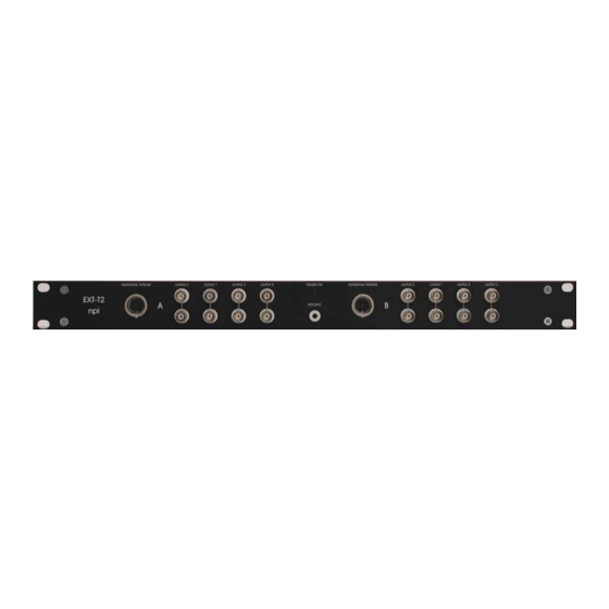
- Page 4 2.1. System Description The EXT-T2 module is an amplifier/filter with headstages for two tetrodes, A and B. The signals recorded from every single tetrode attached to the headstage are amplified and filtered, and linked to the BNC connectors OUTPUT 0 to OUTPUT 3 for every tetrode. Every OUTPUT is available at two BNC connectors.
- Page 5 Tetrode Amplifier User Manual _______________________________________________________________________________________________________________ Jumper Setting (Amplification / Filtering) DC, gain 200, LP 8 kHz DC, gain 500, LP 8 kHz DC, gain 1000, LP 8 kHz DC, gain 200, LP 2 kHz DC, gain 500, LP 2 kHz DC, gain 1000, LP 2 kHz DC, gain 200, LP 500 Hz DC, gain 500, LP 500 Hz...
- Page 6 Figure 2: PCB of one amplifier, location of DIL switch and jumper 2.3. Description of the Rear Panel Figure 3: rear panel view of EXT-T2 GROUND This connector is linked to the internal system ground which has no connection to the 19"...
-
Page 7: Technical Data
Tetrode Amplifier User Manual _______________________________________________________________________________________________________________ 3. Headstage Figure 4: one headstage of the EXT-T2 Headstage Elements Connector for the tetrode (see also Figure 5) REF Not connected GND Ground connector Ground connector (GND) Channel 1 connector (CH0) Channel 3 connector (CH2)
Need help?
Do you have a question about the EXT-T2 and is the answer not in the manual?
Questions and answers