Table of Contents
Advertisement
Quick Links
Advertisement
Table of Contents

Subscribe to Our Youtube Channel
Related Manuals for NPI EXT-10C


Summary of Contents for NPI EXT-10C
- Page 1 OPERATING INSTRUCTIONS AND SYSTEM DESCRIPTION FOR THE EXT-10C EXTRACELLULAR AMPLIFIER MODULE FOR EPMS SYSTEMS VERSION 2.0 npi 2012 npi electronic GmbH, Bauhofring 16, D-71732 Tamm, Germany Phone +49 (0)7141-9730230; Fax: +49 (0)7141-9730240 support@npielectronic.com; http://www.npielectronic.com...
-
Page 2: Table Of Contents
2.3. EPMS-E-07 Housing ....................4 2.4. System Grounding ....................... 5 2.5. Technical Data......................5 3. EXT-10C .......................... 6 3.1. EXT-10C Components ....................6 3.2. System Description...................... 6 3.3. Signal Flow Diagram....................6 3.4. Description of the Front Panel..................7 3.5. Headstage ........................9 Headstage Elements..................... -
Page 3: Safety Regulations
VERY IMPORTANT: Instruments and components supplied by npi electronic are NOT intended for clinical use or medical purposes (e.g. for diagnosis or treatment of humans), or for any other life-supporting system. npi electronic disclaims any warranties for such purpose. Equipment supplied by npi electronic must be operated only by selected, trained and adequately instructed personnel. -
Page 4: Epms-07 Modular Plug-In System
Front covers 2.2. General System Description / Operation The npi EPMS-07 is a m odular system for processing of bioe lectrical signals in electrophysiology. The system is housed in a 19” rackmount cabinet (3U) containing a power supply and has room for up to 7 plug-in units. The plug-in units are connected to power by a bus at the rear panel. -
Page 5: System Grounding
EXT-10C User Manual ___________________________________________________________________________ Figure 2: PWR-03D rear panel view Note: This power supply is intended to be used with npi EPMS-E systems only. 2.4. System Grounding The 19" cabinet is grounded by the power ca ble through the ground pin of the m ains connector (= protective earth). -
Page 6: Ext-10C
The system consists of a m odule for the npi EPMS-07 modular system and a small headstage with a holding bar. -
Page 7: Description Of The Front Panel
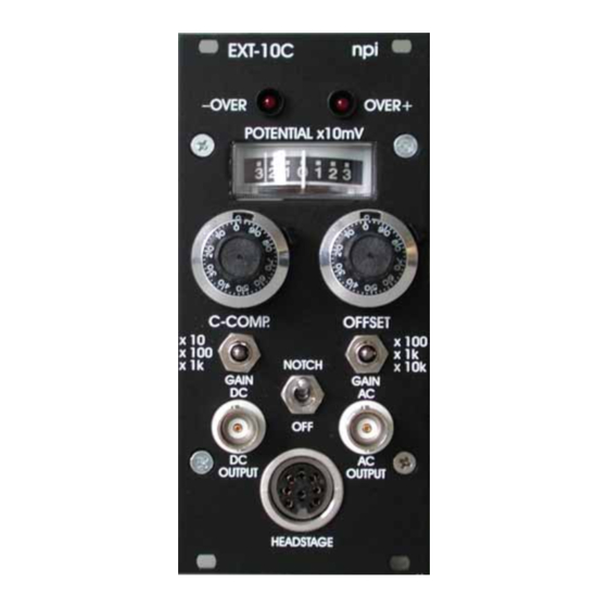
___________________________________________________________________________ Description of the Front Panel 3.4. Figure 3: EXT-10C front panel view In the following description of the front panel elements each elem ent has a number tha t is related to that in Fi gure 3. The number is followed by th e name (in uppercase letters) written on the front panel and the type of the element (in lowercase letters). - Page 8 EXT-10C User Manual ___________________________________________________________________________ (3) GAIN DC switch Switch to set the GAIN of the outgoing DC signal. Three GAIN factors are available: x10, x100 or x1k. (4) C-COMP. potentiometer Control for com pensation of stray capaciti es of the m icroelectrode (10 turn potentiometer, range 0-20 pF).
-
Page 9: Headstage
Very Important: EXT 10C headstages are always labeled “EXT” (see Figure 4) and must not be exchanged with headstages from npi electronic’s desktop EXT amplifiers, e.g. the EXT-2F which is labeled “EXT-02”! Also Important: The shield of the BNC connector of the headstage is connected to driven shield, and must not be connected to ground. - Page 10 EXT-10C User Manual ___________________________________________________________________________ If differential m easurement is not required (single-ended measurement configuration, see Figure 5), the REF inp ut must be connected to ground (GND). The amplifier is in an undefined state, if the REF is left open, an...
-
Page 11: Literature
EXT-10C User Manual ___________________________________________________________________________ 4. Literature Barmashenko, G., Eysel, U. T., & Mittm ann, T. (2003). Changes in intracellular calcium transients and LTP in the surround of visual cortex lesions in rats. Brain Res. 990, 120- 128. Boulton, A. A., Baker, G. B. & Va nderwolf, C. -
Page 12: Technical Data
EXT-10C User Manual ___________________________________________________________________________ Technical Data Differential Input: CMR >90 dB at 1 kHz (tested with 0 input resistance) Input resistance: >10 , range ±1 V Output DC: selectable gain (x10, x100, x1k) Output range: ±12 V into 1 k / ±1 V into 50 load...
Need help?
Do you have a question about the EXT-10C and is the answer not in the manual?
Questions and answers