Advertisement
Advertisement
Table of Contents

Subscribe to Our Youtube Channel
Related Manuals for NPI R/I-T1DX


Summary of Contents for NPI R/I-T1DX
- Page 1 OPERATING INSTRUCTIONS AND SYSTEM DESCRIPTION FOR THE R/I-T1DX ELECTRODE RESISTANCE TEST CURRENT INJECTION VERSION 1.4 npi 2013 npi electronic GmbH, Bauhofring 16, D-71732 Tamm, Germany Phone +49 (0)7141-9730230; Fax: +49 (0)7141-9730240 support@npielectronic.com; http://www.npielectronic.com...
- Page 2 _______________________________________________________________________________________________________________ Table of Contents 1. Safety Regulations ......................3 2. R/I-T1DX Resistance Test / Current Injection ..............4 2.1. Description of the Rear Panel ..................6 2.2. Frequency and Amplitude of Current Injection Pulse ..........7 3. Technical Data ........................7 ___________________________________________________________________________ version 1.4...
- Page 3 VERY IMPORTANT: Instruments and components supplied by npi electronic are NOT intended for clinical use or medical purposes (e.g. for diagnosis or treatment of humans), or for any other life-supporting system. npi electronic disclaims any warranties for such purpose. Equipment supplied by npi electronic must be operated only by selected, trained and adequately instructed personnel.
- Page 4 _______________________________________________________________________________________________________________ 2. R/I-T1DX Resistance Test / Current Injection The R/I-T1DX device allows measurement of the resistance of electrodes connected to an EXT-16DX amplifier. It can function also for injection of current (up to ±100 nA) through a single electrode or through all electrodes simultaneously. The functions are selected by a switch and indicated by an LED.
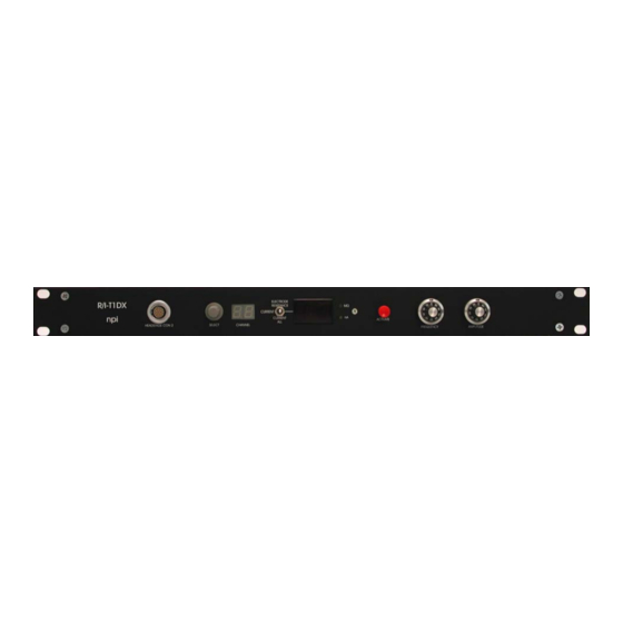
- Page 5 R/I-T1DX User Manual _______________________________________________________________________________________________________________ CHANNEL SELECT indicator LED (XX) indicating the selected CHANNEL for current injection or to be tested for resistance. The indicator starts at 00, e.g. 02 indicates function at CHANNEL 3 (see also #2). ELECTRODE RESISTANCE / CURRENT / CURRENT ALL switch Switch for selecting ELECTRODE RESISTANCE test, CURRENT injection for the selected channel or CURRENT injection for all channels.
- Page 6 The following connectors are located at the rear panel. TO EXT-16DX connector SubD connector for connecting the sixteen channel extracellular amplifier EXT-16DX. The EXT-16DX amplifier provides also the operating voltage for the R/I-T1DX through this cable. AUX connector (optional) Customized auxiliary connector.
- Page 7 R/I-T1DX User Manual _______________________________________________________________________________________________________________ 2.2. Frequency and Amplitude of Current Injection Pulse Frequency and amplitude of current injection are dependent on each other according to where I is the capacitive current, C is the capacitor in the amplifier headstage (3.3 pF) , dU/dt is the change of the voltage amplitude of the triangle over time.
Need help?
Do you have a question about the R/I-T1DX and is the answer not in the manual?
Questions and answers