Table of Contents
Advertisement
Quick Links
OPERATING INSTRUCTIONS AND
SYSTEM DESCRIPTION OF THE
SEC-03M
SINGLE ELECTRODE CLAMP
AMPLIFIER MODULE FOR EPMS
SYSTEMS
VERSION 1.8
npi 2014
npi electronic GmbH, Bauhofring 16, D-71732 Tamm, Germany
Phone +49 (0)7141-9730230; Fax: +49 (0)7141-9730240
support@npielectronic.com; http://www.npielectronic.com
Advertisement
Table of Contents

Subscribe to Our Youtube Channel
Related Manuals for NPI SEC-03M


Summary of Contents for NPI SEC-03M
- Page 1 OPERATING INSTRUCTIONS AND SYSTEM DESCRIPTION OF THE SEC-03M SINGLE ELECTRODE CLAMP AMPLIFIER MODULE FOR EPMS SYSTEMS VERSION 1.8 npi 2014 npi electronic GmbH, Bauhofring 16, D-71732 Tamm, Germany Phone +49 (0)7141-9730230; Fax: +49 (0)7141-9730240 support@npielectronic.com; http://www.npielectronic.com...
-
Page 2: Table Of Contents
3.1. Why a Single Electrode Clamp? .................. 8 3.2. Principle of Operation ....................10 Major Advantages of the npi SEC System ..............12 3.3. Advantages of the Modular SEC-03M System ............12 SEC-03M System ....................... 13 ... - Page 3 12.3. Tuning Procedures for VC Controllers ................ 50 Practical Implications ....................51 Literature about npi single electrode clamp amplifiers ..........53 13.1. Paper in Journals ......................53 13.2. Books ........................... 64 ...
-
Page 4: About This Manual
SEC-03M User Manual ________________________________________________________________________________________________________________ About this Manual This manual should help to setup and use SEC systems correctly and to perform reliable experiments. If you are not familiar with the use of instruments for intracellular recording of electrical signals please read the manual completely. The experienced user should read at least chapters 1, 4, 8 and 10. -
Page 5: Safety Regulations
VERY IMPORTANT: Instruments and components supplied by npi electronic are NOT intended for clinical use or medical purposes (e.g. for diagnosis or treatment of humans), or for any other life-supporting system. npi electronic disclaims any warranties for such purpose. Equipment supplied by npi electronic must be operated only by selected, trained and adequately instructed personnel. -
Page 6: Epms-07 Modular Plug-In System
2.1. General System Description / Operation The npi EPMS-07 is a modular system for processing of bioelectrical signals in electrophysiology. The system is housed in a 19” rackmount cabinet (3U) has room for up to 7 plug-in units. The plug-in units are connected to power by a bus at the rear panel. -
Page 7: System Grounding
SEC-03M User Manual ________________________________________________________________________________________________________________ Figure 1: PWR-03D front panel view Figure 2: PWR-03D rear panel view Note: This power supply is intended to be used with npi EPMS-E systems only. System Grounding 2.5. EPMS-07 The 19" cabinet is grounded by the power cable through the ground pin of the mains connector (= protective earth). -
Page 8: Introduction
SEC-03M User Manual ________________________________________________________________________________________________________________ 3. Introduction npi electronic’s SEC (Single Electrode Clamp) systems are based on the newest developments in the field of modern electronics and control theory (see also chapter 11). These versatile current/voltage clamp amplifiers permit extremely rapid switching between current injection and current-free recording of true intracellular potentials. - Page 9 SEC-03M User Manual ________________________________________________________________________________________________________________ Figure 4: Model circuit for whole cell patch clamp recording using a suction electrode : membrane capacitance, C : electrode stray capacitance, R : electrode stray resistance, R : membrane resistance Figure 5: Model circuit intracellular...
-
Page 10: Principle Of Operation
R during potential measurement. This is the strategy employed in npi electronic’s SEC amplifier systems. The SEC amplifiers inject current and record the potential in an alternating mode (switched mode). Therefore, this technique is called discontinuous SEVC. This ensures that no current... - Page 11 ________________________________________________________________________________________________________________ Figure 7: principle of SEVC operation Figure 6 and Figure 7 illustrate the basic circuitry and operation of npi SEC voltage clamp amplifiers. A single microelectrode penetrates the cell or is connected to the cell interior in the whole-cell configuration of the patch clamp technique.
-
Page 12: Major Advantages Of The Npi Sec System
SEC-03M in one 19” EPMS-07 housing, e.g. for recording from coupled cells simultaneously. For recording from one cell only, it is recommended to add one or two filters to the SEC-03M module. Such a recording system can further be enhanced by adding a stimulus isolator, a iontophoretic amplifier or a controller for pressure ejection. -
Page 13: Sec-03M System
________________________________________________________________________________________________________________ 4. SEC-03M System 4.1. SEC-03M Components The following items are shipped with the SEC-03M system: Amplifier module for the EPMS-07 system Headstage GND- and DRIVEN SHIELD (2.6 mm banana plug) connectors Please open the box and inspect contents upon receipt. If any components appear damaged or... -
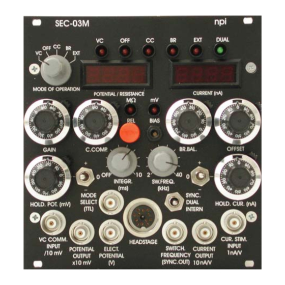
Page 14: Description Of The Front Panel
Description of the Front Panel 4.2. Figure 8: SEC-03M front panel view In the following description of the front panel elements each element has a number that is related to that in Figure 8. The number is followed by the name (in uppercase letters) written on the front panel and the type of the element (in lowercase letters). - Page 15 (3) MODE OF OPERATION LEDs (VC, OFF, CC, BR, EXT, DUAL) LEDs indicating the active mode of operation (see also #1). If operated together with the HVC-03M module the DUAL LED indicates that the SEC-03M works in two electrode voltage clamp mode. (4) M / mV LEDs LEDs indicating that RESISTANCE (M) or POTENTIAL (mV) is revealed in...
- Page 16 SEC-03M User Manual ________________________________________________________________________________________________________________ With this trim potentiometer the output current of the headstage (headstage BIAS current) can be tuned to zero (9) HOLD.CUR.(nA) potentiometer and polarity switch 10-turn digital control that presets a continuous command signal for CC mode (HOLD current). Polarity is set by switch to the left of the control (0 is off-position).
- Page 17 SEC-03M User Manual ________________________________________________________________________________________________________________ CURRENT STIMULUS INPUT current stimulus Figure 9: Input-output relation using CUR.STIM. INPUT Important: The current injected through the electrode is always the sum of the input signal at CUR.STIM. INPUT (12) and the holding current set by HOLD.CUR. (9) and polarity switch.
- Page 18 SEC-03M User Manual ________________________________________________________________________________________________________________ (17) POTENTIAL OUTPUT x10 mV connector BNC connector monitoring the recorded membrane potential with a gain of ten. (18) VC COMM. INPUT /10 mV connector BNC connector for an external COMMAND in VC mode (sensitivity: /10, i.e. 0.1 V / V).
-
Page 19: Headstages
5. Headstages 5.1. Standard and low-noise (SEC-HSP) headstages The SEC-03M comes with the standard headstage (range: 120 nA) for connecting glass electrodes with high resistances or suction electrodes for whole cell patch clamp recordings with lower resistances via an electrode holder. - Page 20 HEADSTAGE connector! Figure 11: standard headstage, electrode holder (optional) and electrode holder adapter (optional) of the SEC-03M The standard headstage consists of the following elements (see Figure 11): Headstage cable to amplifier Coarse capacity compensation potentiometer...
-
Page 21: Low-Noise Headstage (Sec-Hsp)
SEC-03M User Manual ________________________________________________________________________________________________________________ 5.2. Low-noise headstage (SEC-HSP) The low-noise / low bias headstage (range: 12 nA, see also Optional accessories in chapter 4.1) has an external capacity compensation and a BNC electrode holder connector. Figure 12: low noise headstage with electrode holder (optional) The headstage is mounted to a non-conducting mounting plate. -
Page 22: Setting Up The Sec-03M System
________________________________________________________________________________________________________________ 6. Setting up the SEC-03M System The following steps should help you set up the SEC-03M correctly. Always adhere to the appropriate safety measures (see chapter 1). Usually the SEC-03M is shipped mounted in an EPMS-07 housing. If a single SEC-03M module is delivered, the user has to mount the module into the EPMS-07 housing. -
Page 23: Passive Cell Model
________________________________________________________________________________________________________________ 7. Passive Cell Model The SEC-03M can be ordered with a passive SEC (Single Electrode Clamp amplifier) cell model as an optional accessory. An active cell model is also available on request (for ref. see Draguhn et al. (1997)). -
Page 24: Connections And Operation
SEC-03M User Manual ________________________________________________________________________________________________________________ Figure 14: Schematic diagram of the passive cell model 7.2. Connections and Operation Connections Turn POWER switch of the amplifier off. a) For simulation of an experiment using a suction electrode Connect the BNC jack of the cell model to the BNC connector P of the headstage. -
Page 25: Connections And Operation
SEC-03M User Manual ________________________________________________________________________________________________________________ Simulation of electrode in the bath Set switch #4, Figure 13 to the lower position. Set switch #5, Figure 13 to GROUND position. The 1 k resistor simulates the resistance of the bath solution. This can be used to train cancellation of offsets, using the bridge balance and using the capacity compensation. - Page 26 SEC-03M User Manual ________________________________________________________________________________________________________________ Leave REF untouched. Switch the CELL membrane switch (see Figure 13) to the desired position. Turn all controls at the amplifier to low values (less than 1) and the OFFSET in the range of 5 and the OSCILLATION SHUTOFF in the DISABLED position.
-
Page 27: Test And Tuning Procedures
SEC-03M User Manual ________________________________________________________________________________________________________________ 8. Test and Tuning Procedures Important: The SEC-03M should be used only in warmed-up condition i.e. 20 to 30 minutes after turning power on. The following test and tuning procedures are necessary for optimal recordings. It is recommended to first connect a cell model to the amplifier to perform some basic adjustments and to get familiar with these procedures. -
Page 28: Electrode Selection
SEC-03M User Manual ________________________________________________________________________________________________________________ First, the headstage electrode connector must be grounded (as if an electrode with a very low resistance were attached). To avoid damage of the headstage amplifiers please use a 10 k resistor (which is small enough compared to a 10-100 M resistor). Now the offset potential of the POTENTIAL output can be tuned to zero. -
Page 29: Bridge Balance (In Br Mode)
SEC-03M User Manual ________________________________________________________________________________________________________________ 8.4. Bridge Balance (in BR mode) If current is passed through an electrode the occurring voltage deflection (potential drop at ) affects the recording of membrane potential in BRIDGE mode. Therefore this deflection must be compensated carefully by means of the BR. BAL. control. This control is calibrated in M. - Page 30 SEC-03M User Manual ________________________________________________________________________________________________________________ Figure 16: Tuning of the BRIDGE BALANCE using 100 M resistor ___________________________________________________________________________ version 1.8 page 30...
-
Page 31: Switching Frequency And Capacitance Compensation (In Switched Modes)
SEC-03M User Manual ________________________________________________________________________________________________________________ 8.5. Switching Frequency and Capacitance Compensation (in switched modes) For accurate measurements in switched mode, it is essential that the capacity of the electrode is fully compensated. Important: Wrong compensation of electrode capacity leads to errors in measurements done in switched mode of the amplifier (see Figure 18). - Page 32 SEC-03M User Manual ________________________________________________________________________________________________________________ > 3f > 2f > 2f >f upper cutoff frequency of the microelectrode switching frequency of the dSEVC sampling frequency of the data acquisition system upper cutoff frequency of the lowpass filter for current recording, upper cutoff frequency of the membrane.
-
Page 33: Capacity Compensation - Tuning Procedure
SEC-03M User Manual ________________________________________________________________________________________________________________ Figure 18: Errors resulting from wrong compensation of the electrode capacity. Original data kindly provided by Ajay Kapur. For details see (Kapur et al., 1998). 8.6. Capacity Compensation - Tuning Procedure First part: basic setting In SEC systems the capacity compensation of the electrode is split into two controls, the coarse control at the headstage and a the fine control at the front panel of the amplifier. - Page 34 SEC-03M User Manual ________________________________________________________________________________________________________________ Figure 19: Tuning of the coarse capacity compensation with an electrode (resistance 100 M) in the bath. Time course of the signal at ELECTRODE POTENTIAL OUTPUT is shown (holding current: -1 nA, switching frequency: 2 kHz).
- Page 35 SEC-03M User Manual ________________________________________________________________________________________________________________ Figure 20: Tuning of the coarse capacity compensation. Time course of the signal at ELECTRODE POTENTIAL OUTPUT is shown (holding current: -1 nA, switching frequency: 2 kHz). A cell model was connected (electrode resistance 100 M).
- Page 36 SEC-03M User Manual ________________________________________________________________________________________________________________ Figure 21: Capacity compensation of the electrode in the bath (electrode resistance: 100 M, Current stimulus: 1 nA, switching frequency: 2 kHz). Current stimulus and electrode potential are shown. ___________________________________________________________________________ version 1.8 page 36...
- Page 37 SEC-03M User Manual ________________________________________________________________________________________________________________ Figure 22: Capacity compensation of the electrode using a cell model (electrode resistance: 100 M, current: 1 nA, cell membrane: 100 M, 100 pF, switching frequency: 2 kHz). Current stimulus and membrane potential are shown. ___________________________________________________________________________ version 1.8...
-
Page 38: Second Part: Fine Tuning
SEC-03M User Manual ________________________________________________________________________________________________________________ Second part: fine tuning Now the basic setting of the CAPACITY COMPENSATION is achieved. Since the electrode parameters change during the experiment (especially after impaling a cell), it is necessary to fine tune the CAPACITY COMPENSATION during the experiment using the C.COMP. -
Page 39: Testing Operation Modes
That allows measurement of ion fluxes across the cell membrane. This is the most complex mode of operation with the SEC-03M. Special precautions must be taken while tuning the control circuit in order avoid stability problems. - Page 40 SEC-03M User Manual ________________________________________________________________________________________________________________ Hint: If the system oscillates as soon as you switch to VC mode, switch back to CC mode and check the settings. GAIN too high? CAPACITY COMPENSATION not properly adjusted, i.e. not overcompensated? INTEGRATOR switch not to OFF? ...
-
Page 41: Sample Experiments
GND at the headstage. Make the basic settings (see chapter 6). Again: It is of major importance that SEC-03M systems are used only in warmed-up condition, i.e. 20 to 30 minutes after turning power on. - Page 42 SEC-03M User Manual ________________________________________________________________________________________________________________ Now the system is preadjusted for measurements in BR mode. Find a cell! Approach the desired cell. There are several indications that the electrode is very close to the cell membrane: the electrode resistance increases (the bridge balance appears undercompensated) extracellular action potentials (APs) are recorded ...
- Page 43 SEC-03M User Manual ________________________________________________________________________________________________________________ Figure 26: Artifacts caused by the recording electrode. The measurements were done in BR mode using a cell model with 100 M membrane resistance, 100 pF membrane capacitance M electrode resistance. compensated (bridge balanced) stray compensated...
-
Page 44: Sample Experiment Using A Suction Electrode
SEC-03M User Manual ________________________________________________________________________________________________________________ 9.2. Sample Experiment using a Suction Electrode If suction electrodes are used for whole cell recordings they are usually called “pipettes”. Thus, in this subchapter “pipette” means “suction electrode” . Figure 27: Model circuit for whole cell patch clamp recording using a suction electrode... - Page 45 SEC-03M User Manual ________________________________________________________________________________________________________________ Start the experiment in BR mode Switch to discontinuous CC mode. The shape of voltage and current traces should not change considerably. If you intend to work in discontinuous VC mode, tune the system in CC mode (see above), then switch to VC mode and adjust the clamp as described in chapters 10 and 12.3.
-
Page 46: Tuning Vc Performance
SEC-03M User Manual ________________________________________________________________________________________________________________ Tuning VC Performance In VC mode there is the problem that the voltage step is often not strictly angular shaped. But, for instance, increasing the clamp speed by tuning the CAPACITY COMPENSATION of the electrode or increasing GAIN also increases noise. Therefore, the settings of the different parameters result always in a compromise between the stability, accuracy, noise and control speed. -
Page 47: Tuning Procedure
Only a P-Controller is used. The response to a command step is slow and has no overshoot (potential output). The response disturbance, e.g. activating channel, is slow and has a large deviation. A PI-Controller is used. The response to a command step is very fast with 4% overshoot (potential output). -
Page 48: Trouble Shooting
2. Exchange the pellet or chloride the silver wire in the agar-bridge 3. Try to find the GND-bridge and disconnect it e.g. by sealing the bath 4. Contact npi Problem 2: Even if no stimulus is given a current flows through the current electrode Possible reason: 1. -
Page 49: Appendix
SEC-03M User Manual ___________________________________________________________________________ Appendix 12.1. Theory of Operation Voltage clamp instruments are closed loop control systems with two inputs external to the control loop. An electronic feedback network is used to force the membrane potential of a cell to follow a voltage command (setpoint input) as fast and as accurately as possible in the presence of incoming disturbances (disturbance input, correlated with the activities of the cell e.g. -
Page 50: Speed Of Response Of Sec Single Electrode Clamps
CC or VC modes the maximum current has to be multiplied with the duty cycle (1/8, 1/4, or 1/2). The maximum current is 15 nA, 30 nA or 60 nA. Remember: The duty cycle of the modular SEC-03M is fixed to 1/4. With the maximum current determined electronically by the current source (for R <100 M) -
Page 51: Practical Implications
SEC-03M User Manual ___________________________________________________________________________ The initial settings using GAIN only guarantee only a stable clamp that is not very accurate and insufficiently rapid for certain types of experiments, e.g. investigation of fast voltage- activated ion channels or gating currents. Thus, for successful and reliable experiments, it is necessary to tune the clamp loop. - Page 52 SEC-03M User Manual ___________________________________________________________________________ Very important: All parameters that influence clamp performance (microelectrode offset, capacity compensation, etc.) must be optimally tuned before starting the PI controller tuning procedure. The tuning procedure involves the following steps: Again: The main criterion of tuning is the amount of overshoot seen at the potential output.
-
Page 53: Literature About Npi Single Electrode Clamp Amplifiers
SEC-03M User Manual ___________________________________________________________________________ Literature about npi single electrode clamp amplifiers 13.1. Paper in Journals Recording Methods and Voltage Clamp Technique Dietzel, I. D., Bruns, D., Polder, H. R. and Lux, H. D. (1992). Voltage Clamp Recording, in Kettenmann, H. and R. Grantyn (eds.) Practical Electrophysiological Methods, Wiley- Liss, NY. - Page 54 SEC-03M User Manual ___________________________________________________________________________ Comparison of recording methods (sharp electrode, whole cell, perforated patch) Jarolimek, W. and Miseld, U. (1993). 4-Aminopyridine-induced synaptic GABA-B currents in granule cells of the guinea-pig hippocampus. Pflügers Arch. 425, 491-498. Kapur, A., Yeckel, M. F., Gray, R. and Johnston, D. (1998). L-Type calcium channels are required for one form of hippocampal mossy fiber LTP.
- Page 55 SEC-03M User Manual ___________________________________________________________________________ Double cell voltage clamp method Dhein, St. (1998). Cardiac Gap Junction Channels, Physiology, Regulation, Pathophysiology and Pharmacology, Karger, Basel. Double Cell Recordings / Gap Junctions Bedner, P., Niessen, H., Odermatt, B., Willecke, K., & Harz, H. (2003). A method to determine the relative cAMP permeability of connexin channels.
- Page 56 SEC-03M User Manual ___________________________________________________________________________ Intra- and extracellular drug application during single electrode clamping Scuvee-Moreau, J., Liegeois, J. F., Massotte, L., & Seutin, V. (2002). Methyl-laudanosine: a new pharmacological tool to investigate the function of small-conductance Ca(2+)- activated K(+) channels. J Pharmacol.Exp.Ther. 302, 1176-1183.
- Page 57 SEC-03M User Manual ___________________________________________________________________________ Tracer injection and intracellular recording Poulet, J. F. & Hedwig, B. (2006). The cellular basis of a corollary discharge. Science. 311, 518-522. Röhrig, G., Klausa, G., & Sutor, B. (1996). Intracellular acidification reduced gap junction coupling between immature rat neocortical pyramidal neurons.
- Page 58 SEC-03M User Manual ___________________________________________________________________________ LTP / LDP /LTD Investigations Azad, S. C., Monory, K., Marsicano, G., Cravatt, B. F., Lutz, B., Zieglgansberger, W., & Rammes, G. (2004). Circuitry for associative plasticity in the amygdala involves endocannabinoid signaling. J Neurosci 24, 9953-9961.
- Page 59 SEC-03M User Manual ___________________________________________________________________________ Performance test with active cell model Draguhn, A., Pfeiffer, M., Heinemann, U. and Polder, H. R. (1997). A simple hardware model for the direct observation of voltage-clamp performance under realistic conditions. J.Neurosci.Meth. 78, 105-113. Intra- and extracellular low noise recording ...
- Page 60 SEC-03M User Manual ___________________________________________________________________________ Recordings from Crustacea DiCaprio, R. A. (2003). Nonspiking and Spiking Proprioceptors in the Crab: Nonlinear Analysis of Nonspiking TCMRO Afferents. J Neurophysiol. 89, 1826-1836. DiCaprio, R. A. (2004). Information Transfer Rate of Nonspiking Afferent Neurons in the Crab.
- Page 61 SEC-03M User Manual ___________________________________________________________________________ Daw, M. I., Bannister, N. V., & Isaac, J. T. (2006). Rapid, activity-dependent plasticity in timing precision in neonatal barrel cortex. J Neurosci. 26, 4178-4187. Dong, Y., Nasif, F. J., Tsui, J. J., Ju, W. Y., Cooper, D. C., Hu, X. T., Malenka, R. C., &...
- Page 62 SEC-03M User Manual ___________________________________________________________________________ Kohling, R., Koch, U. R., Hamann, M., & Richter, A. (2004). Increased excitability in cortico-striatal synaptic pathway in a model of paroxysmal dystonia. Neurobiol.Dis. 16, 236-245. Ludwar, B. C., Westmark, S., Buschges, A., & Schmidt, J. (2005). Modulation of membrane potential in mesothoracic moto- and interneurons during stick insect front-leg walking.
- Page 63 SEC-03M User Manual ___________________________________________________________________________ bone marrow-derived mononuclear cells--an in vitro-model. European Journal of Cardio- Thoracic Surgery 27, 104-110. Reiprich, P., Kilb, W., & Luhmann, H. J. (2005). Neonatal NMDA Receptor Blockade Disturbs Neuronal Migration in Rat Somatosensory Cortex In Vivo. Cerebral Cortex 15, 349-358.
-
Page 64: Books
SEC-03M User Manual ___________________________________________________________________________ 13.2. Books Boulton, A.A., Baker, G.B. and Vanderwolf, C.H. (eds.) (1990) Neurophysiological techniques. Basic methods and concepts. Humana Press, Clifton, New Jersey. Cole, K.S. (1968) Membranes ions and impulses. University of California Press, Berkely, ... -
Page 65: Sec-03M Specifications - Technical Data
SEC-03M User Manual ___________________________________________________________________________ SEC-03M Specifications – Technical Data MODES OF OPERATION Voltage Clamp mode (discontinuous) Current Clamp mode (discontinuous) OFF: Current- and Voltage Clamp disabled Bridge Mode (continuous CC) EXT: External control mode; the mode of operation can be set by a TTL pulse applied to the MODE SELECT BNC. - Page 66 SEC-03M User Manual ___________________________________________________________________________ ELECTRODE PARAMETER CONTROLS Offset: ten-turn control, ±200 mV Capacity compensation: range 0-30 pF adapts compensation circuit to electrode parameters coarse control at headstage fine control at front panel: ten-turn potentiometer BANDWIDTH and SPEED OF RESPONSE Full power bandwidth (R = 0): >100 kHz...
- Page 67 SEC-03M User Manual ___________________________________________________________________________ SPEED of RESPONSE (VC Mode) 1 % settling time: <80 µs for 10 mV step and <800 µs for 50 mV step applied to a cell model = 100 M, R = 50 M, C = 470 pF, duty cycle = 25%, switching frequency =...
-
Page 68: Index
SEC-03M User Manual ___________________________________________________________________________ Index abbreviations 4 MODE OF OPERATION LEDs 15 Absolute value optimum 51 MODE OF OPERATION switch 15 accessories 13 MODE SELECT connector 18 AVO-method 51 model circuit sharp electrode 9, 41 basic installation 22 model circuit suction (patch) electrode 9...
Need help?
Do you have a question about the SEC-03M and is the answer not in the manual?
Questions and answers