Table of Contents
Advertisement
Quick Links
Advertisement
Table of Contents

Related Manuals for NPI SEC-05X


Summary of Contents for NPI SEC-05X
- Page 1 OPERATING INSTRUCTIONS AND SYSTEM DESCRIPTION OF THE SEC-05X SINGLE-ELECTRODE CLAMP AMPLIFIER VERSION 2.0 npi 2015 npi electronic GmbH, Bauhofring 16, D-71732 Tamm, Germany Phone +49 (0)7141-9730230; Fax: +49 (0)7141-9730240 support@npielectronic.com; http://www.npielectronic.com...
-
Page 2: Table Of Contents
2. Introduction ......................... 6 2.1. Why a Single-Electrode Clamp? ................. 6 2.2. Principle of Operation ....................8 Major advantages of the npi SEC System ..............10 3. SEC-05X System ........................ 10 3.1. SEC-05X Components ....................10 3.2. Description of the Front Panel ..................12 3.3. - Page 3 12.3. Tuning Procedures for VC Controllers ................ 56 Practical Implications ....................56 Literature ........................58 13.1. Papers in Journals and Book Chapters about npi Single-electrode Clamp Amplifiers 58 13.2. Books ........................... 70 SEC-05X Specifications – Technical Data ..............71 Index ..........................74 version 2.0...
-
Page 4: About This Manual
SEC-05X User Manual About this Manual This manual should help the user to setup and use SEC systems correctly and to perform reliable experiments. If you are not familiar with the use of instruments for intracellular recording of electrical signals please read the manual completely. The experienced user should read at least chapters 1, 3, 7 and 10. -
Page 5: Safety Regulations
VERY IMPORTANT: Instruments and components supplied by npi electronic are NOT intended for clinical use or medical purposes (e.g. for diagnosis or treatment of humans), or for any other life-supporting system. npi electronic disclaims any warranties for such purpose. Equipment supplied by npi electronic must be operated only by selected, trained and adequately instructed personnel. -
Page 6: Introduction
SEC-05X User Manual 2. Introduction Npi electronic’s SEC (Single-Electrode Clamp) systems are based on the newest developments in the field of modern electronics and control theory (see also chapter 8). These versatile current/voltage clamp amplifiers permit extremely rapid switching between current injection and current-free recording of true intracellular potentials. - Page 7 SEC-05X User Manual Figure 1: Model circuit whole-cell patch-clamp recording. : membrane capacitance, C : electrode stray capacitance, R : access stray resistance, R : membrane resistance Figure 2: Model circuit intracellular recording using sharp electrode : membrane capacitance, C...
-
Page 8: Principle Of Operation
R during potential measurement. This is the strategy employed in npi electronic’s SEC amplifier systems. The SEC amplifiers inject current and record the potential in an alternating mode (switched mode). Therefore, this technique is called discontinuous SEVC (dSEVC). This ensures that no... - Page 9 SEC-05X User Manual Figure 4: Principle of dSEVC operation Figure 3 and Figure 4 illustrate the basic circuitry and operation of npi SEC voltage clamp amplifiers. A single microelectrode penetrates the cell or is connected to the cell interior in the whole-cell configuration of the patch-clamp technique.
-
Page 10: Major Advantages Of The Npi Sec System
Major advantages of the npi SEC System Npi electronic’s SEC amplifiers are the only systems that use a PI controller to avoid recordings artefacts known to occur in other single-electrode clamp systems (“clamping of the electrode”). The PI controller design increases gain to as much as 100 µA/V in frequencies less than one-fourth the switching frequency. - Page 11 SEC-05X User Manual Optional accessories: Electrode holder set with one holder for sharp microelectrodes (without port), one patch ➪ electrode holder (with one port) and an electrode holder adapter (SEC-EH-SET) Active cell model (SEC-MODA) ➪ Passive cell model (SEC-MOD, see chapter 6) ➪...
-
Page 12: Description Of The Front Panel
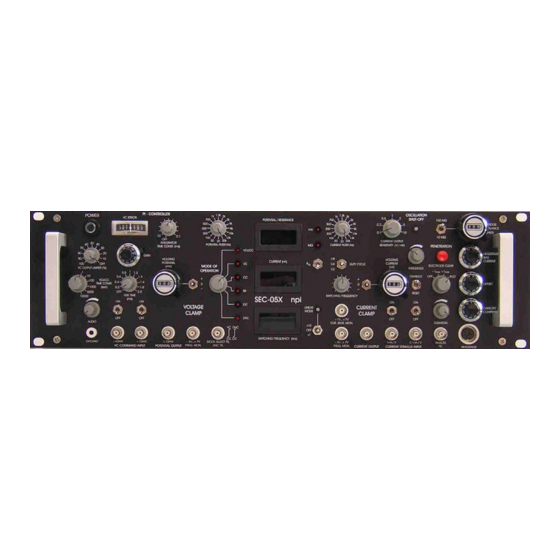
SEC-05X User Manual 3.2. Description of the Front Panel Figure 5: SEC-05X front panel view version 2.0 page 12... - Page 13 SEC-05X User Manual In the following description of the front panel elements each element has a number that is related to that in Figure 5. The number is followed by the name (in uppercase letters) written on the front panel and the type of the element (in lowercase letters). Then, a short description of the element is given.
- Page 14 SEC-05X User Manual (7) POTENTIAL FILTER switch 16-position switch to set the corner frequency of the Bessel filter. The setting is monitored by #42. (8) MODE OF OPERATION switch The MODE OF OPERATION switch has 6 positions. The active mode of operation is indicated by a red LED next to the operation mode name.
- Page 15 SEC-05X User Manual (9) CURRENT (nA) display LED-Display for the CURRENT passed through the electrode in nA. (10) POTENTIAL / RESISTANCE display LED-Display for the POTENTIAL at the electrode tip in mV or the electrode RESISTANCE in MΩ Note: When measuring electrode resistance in LINEAR x10 mode, the reading at the RESISTANCE display (#10) must be multiplied by 10 to obtain the correct value.
- Page 16 SEC-05X User Manual (16) CURRENT OUTPUT SENSITIVITY (V/nA) switch 7-position switch to set the CURRENT OUTPUT gain. The setting is monitored by #36. OSCILLATION SHUT-OFF unit In SHUTOFF condition the amplifier is set into CC mode and all outputs (including holding current) and CAPACITY COMPENSATION are disabled.
- Page 17 SEC-05X User Manual With this 10 turn potentiometer the output current of the headstage (headstage BIAS current) can be tuned to 0 (see chapter 7.1). (25) OFFSET potentiometer Control to compensate the electrode potential (ten-turn potentiometer, symmetrical, i.e. 0 mV = 5 on the dial), range: ±200 mV (see chapter 7.3).
- Page 18 SEC-05X User Manual (35) CURRENT OUTPUT connector BNC connector providing the CURRENT OUTPUT signal after passing the CURRENT FILTER (see #13) and the CURRENT OUTPUT SENSITIVITY switch (see #16). (36) CUR. SENS. MON. +1 V…+7 V BNC output connector monitoring the setting of CURRENT OUTPUT SENSITIVITY V/µA switch (#16).
- Page 19 SEC-05X User Manual BNC connector monitoring the POTENTIAL at the tip of the electrode (sensitivity: x10 mV). Important: In LINEAR MODE x10, the voltage output (POTENTIAL OUTPUT x10 mV BNC connector) is set to x1 mV, i.e. 1 V is 1 V (and not 100 mV as in LIN mode x1).
-
Page 20: Description Of The Rear Panel
3.3. Description of the Rear Panel Figure 6: SEC-05X rear panel view (the numbers are related to those in the text below). (1) FUSE holder Holder for the line fuse and line voltage selector. For changing the fuse or selecting line voltage open the flap using a screw driver. -
Page 21: Headstages
4. Headstages 4.1. Standard Headstages The SEC-05X comes with the standard headstage (range: ±120 nA) for connecting glass electrodes with high resistances or patch electrodes for whole-cell patch-clamp recordings with lower resistances via an electrode holder. A low-noise current headstage for measurement of small currents, a headstage with differential input and a headstage for extracellular measurements is also available (see chapter 4.2). - Page 22 HEADSTAGE connector! Figure 7: Standard headstage, electrode holder (optional) and electrode holder adapter (optional) of the SEC-05X The standard headstage consists of the following elements (see Figure 7): Headstage cable to amplifier...
-
Page 23: Low-Noise Headstage (Sec-Hsp)
SEC-05X User Manual 4.2. Low-noise Headstage (SEC-HSP) The low-noise / low-bias headstage (range: ±12 nA, see also Optional accessories in chapter 3.1) has an external capacity compensation and a BNC electrode holder connector. Figure 8: Low-noise headstage with electrode holder (optional) The headstage is mounted to a non-conducting mounting plate. -
Page 24: Setting Up The Sec-05X System
SEC-05X User Manual 5. Setting up the SEC-05X System The following steps should help you set up the SEC-05X correctly. Always adhere to the appropriate safety measures (see chapter 1). It is assumed that a cell model will be attached. -
Page 25: Cell Model Description
SEC-05X User Manual 6.1. Cell Model Description Figure 9: SEC-MOD passive cell model 1, 3: connectors for the headstage, 1: electrode resistance: 100 MΩ, 3: electrode resistance: 5 MΩ GND ground connector, to be connected to GND jack of the headstage CELL: switch for cell membrane representing a membrane of either 100 MΩ... -
Page 26: Connections And Operation
SEC-05X User Manual Figure 10: Schematic diagram of the passive cell model 6.2. Connections and Operation Connections Turn POWER switch of the amplifier off. a) For simulation of an experiment using a patch electrode Connect the BNC jack of the cell model to the BNC connector P of the headstage. - Page 27 SEC-05X User Manual Simulation of electrode in the bath Set switch #4, Figure 9 to the lower position. Set switch #5, Figure 9 to GROUND position. The 1 kΩ resistor simulates the resistance of the bath solution. This can be used to train cancellation of offsets, using the bridge balance and using the capacity compensation.
-
Page 28: Test And Tuning Procedures
SEC-05X User Manual 7. Test and Tuning Procedures Important: The SEC-05X should be used only in warmed-up condition i.e. 20 to 30 minutes after turning power on. The following test and tuning procedures are necessary for optimal recordings. It is recommended to first connect a cell model to the amplifier to perform some basic adjustments and to get familiar with these procedures. -
Page 29: Electrode Selection
SEC-05X User Manual First, the headstage electrode connector must be grounded (as if an electrode with a very low resistance were attached). To avoid damage of the headstage amplifiers please use a 10 kΩ resistor (which is small enough compared to a 10-100 MΩ resistor). Now the offset potential of the POTENTIAL OUTPUT can be tuned to zero. -
Page 30: Bridge Balance (In Br Mode)
SEC-05X User Manual 7.4. Bridge Balance (in BR mode) If current is passed through an electrode the occurring voltage deflection (potential drop at ) affects the recording of membrane potential in BRIDGE mode. Therefore this deflection must be compensated carefully by means of the BRIDGE BALANCE control (#21,#23). This control is calibrated in MΩ. - Page 31 SEC-05X User Manual Figure 12: Tuning of the BRIDGE BALANCE using 100 MΩ resistor version 2.0 page 31...
-
Page 32: Switching Frequency And Capacitance Compensation (In Switched Modes)
SEC-05X User Manual 7.5. Switching Frequency and Capacitance Compensation (in switched modes) For accurate measurements in switched mode, it is essential that the capacity of the electrode is fully compensated. Important: Wrong compensation of electrode capacity leads to errors in measurements done in switched mode of the amplifier (see Figure 14). - Page 33 SEC-05X User Manual > 3f > 2f > 2f >f upper cutoff frequency of the microelectrode switching frequency of the dSEVC sampling frequency of the data acquisition system upper cutoff frequency of the lowpass filter for current recording, upper cutoff frequency of the membrane.
-
Page 34: Capacity Compensation - Tuning Procedure
SEC-05X User Manual Important: Artifact-free dSEVC is only possible when the switching frequency and the capacity compensation can be adjusted such that the electrode potential is in a steady state during the sampling intervals. (see Figure 13: Microelectrode artifact settling). - Page 35 SEC-05X User Manual Important: If you use a model cell (e.g. to train yourself in adjusting the capacity compensation) the capacity of the model cell is always present. Thus, you will get an approximately square shaped signal with a slight slope as shown in Figure 16 (lower panel).
- Page 36 SEC-05X User Manual Figure 15: Tuning of the coarse capacity compensation with an electrode (resistance 100 MΩ) in the bath. Time course of the signal at ELECTRODE POTENTIAL OUTPUT (rear panel) is shown (holding current: -1 nA, switching frequency: 2 kHz).
- Page 37 SEC-05X User Manual Figure 16: Tuning of the coarse capacity compensation. Time course of the signal at ELECTRODE POTENTIAL OUTPUT (rear panel) is shown (holding current: -1 nA, switching frequency: 2 kHz). A cell model was connected (electrode resistance 100 MΩ).
- Page 38 SEC-05X User Manual Figure 17: Capacity compensation of the electrode in the bath (electrode resistance: 100 MΩ, Current stimulus: 1 nA, switching frequency: 2 kHz). Current stimulus and electrode potential are shown. version 2.0 page 38...
- Page 39 SEC-05X User Manual Figure 18: Capacity compensation of the electrode using a cell model (electrode resistance: 100 MΩ, current: 1 nA, cell membrane: 100 MΩ, 100 pF, switching frequency: 2 kHz). Current stimulus and membrane potential are shown. version 2.0...
-
Page 40: Second Part: Fine Tuning
SEC-05X User Manual Second part: fine tuning Now the basic setting of the CAPACITY COMPENSATION is achieved. Since the electrode parameters change during the experiment (especially after impaling a cell), it is necessary to fine-tune the CAPACITY COMPENSATION during the experiment using the C.COMP. -
Page 41: Testing Operation Modes
That allows measurement of ion fluxes across the cell membrane. This is the most complex mode of operation with the SEC-05X. Special precautions must be taken while tuning the control circuit in order to avoid stability problems. - Page 42 SEC-05X User Manual The upper display should show the holding potential of –50 mV and the lower display the holding current of –0.5 nA (according to Ohm's law). Hint: If the system oscillates as soon as you switch to VC mode, switch back to CC mode and check the settings.
-
Page 43: Special Modes Of Operation
SEC-05X User Manual 8. Special Modes of Operation 8.1. Dynamic Hybrid Clamp (DHC) Mode (optional) General Description The “Dynamic Hybrid Clamp” (DHC) mode is used for investigations of ionic conductances in voltage clamp (VC) mode following action potentials in current clamp (CC) mode. In CC mode an action potential is detected by a spike detector and triggers a timing unit. -
Page 44: Vcccc Mode (Optional)
VC) mode is used for performing accurate current clamp recordings in the presence of membrane potential oscillations. The npi single and two electrode current and voltage-clamp amplifiers (npi SEC 05X/10LX; npi TEC-05X series) have been modified in a way that slow membrane potential oscillations are exactly controlled by the voltage-clamp module without affecting faster responses, e.g. -
Page 45: Current Clamp Input
SEC-05X User Manual The VCcCC mode is controlled through two front panel elements (located in the VC part of the front panel): the MODE OF OPERATION rotary switch (#8) and a rotary switch to set the time constants (10-100-1000, 5000 and 10000 sec) for the low-pass filter (#51). To start using the VCcCC mode, the amplifier must be tuned accurately in the fast VC mode. -
Page 46: Sample Experiments
GND at the headstage. Make the basic settings (see chapter 5). Again: It is of major importance that SEC-05X systems are used only in warmed-up condition, i.e. 20 to 30 minutes after turning power on. - Page 47 SEC-05X User Manual Approach the desired cell. There are several indications that the electrode is very close to the cell membrane: the electrode resistance increases (the bridge balance appears undercompensated) extracellular action potentials (APs) are recorded Apply a BUZZ to the electrode.
- Page 48 SEC-05X User Manual Figure 22: Artifacts caused by the recording electrode. The measurements were done in BR mode using a cell model with 100 MΩ membrane resistance, 100 pF membrane capacitance MΩ electrode resistance. compensated (bridge balanced) stray compensated compensated...
-
Page 49: Sample Experiment Using A Patch Electrode
SEC-05X User Manual 9.2. Sample Experiment using a Patch Electrode If patch electrodes are used for whole cell recordings they are usually called “pipettes”. Thus, in this subchapter “pipette” means “patch electrode” . Figure 23: Model circuit for whole cell patch-clamp recording using a patch electrode... - Page 50 SEC-05X User Manual Start the experiment in BR mode Switch to discontinuous CC mode. The shape of voltage and current traces should not change considerably. If you intend to work in discontinuous VC mode, tune the system in CC mode (see above), then switch to VC mode and adjust the clamp as described in chapters 10 and 12.3.
-
Page 51: Tuning Vc Performance
SEC-05X User Manual Tuning VC Performance A notorious problem in VC mode is the insufficient steepness of voltage steps. . In principle, this problem can be alleviated by tuning the CAPACITY COMPENSATION of the electrode or increasing GAIN to increase clamp speed. However, these tuning procedures may also increase noise. -
Page 52: Tuning Procedure
SEC-05X User Manual Only a P-Controller is used. The response to a command step is slow and has no overshoot (potential output). response disturbance, e.g. activating channel, is slow and has a large deviation. A PI-Controller is used. response to a command step is very fast with 4% overshoot (potential output). -
Page 53: Trouble Shooting
SEC-05X User Manual Trouble Shooting In the following section some common problems, possible causes, and their solutions are described. Important: Please note that the suggestions for solving the problems are only hints and may not work. In a complex setup it is impossible to analyze problems without knowing details. In... -
Page 54: Appendix
SEC-05X User Manual Appendix 12.1. Theory of Operation Voltage clamp instruments are closed-loop control systems with two inputs external to the control loop. An electronic feedback network is used to force the membrane potential of a cell to follow a voltage command (set-point input) as fast and as accurately as possible in the presence of incoming disturbances (disturbance input, correlated with the activities of the cell e.g. -
Page 55: Speed Of Response Of Sec Single-Electrode Clamps
SEC-05X User Manual The clamp performance can be increased considerably if the influence of the current injecting electrode is excluded as far as possible from the clamp loop since the electrode resistance is nonlinear. This is achieved if the output of the clamp system is a current source rather than a voltage source. -
Page 56: Tuning Procedures For Vc Controllers
SEC-05X User Manual 12.3. Tuning Procedures for VC Controllers The initial settings using GAIN only guarantee a stable clamp that is not very accurate and not fast enough for certain types of experiments, e.g. investigation of fast voltage-activated ion channels or gating currents. Thus, for successful and reliable experiments, it is necessary to tune the clamp loop. - Page 57 SEC-05X User Manual output. Since the SO method provides the tightest control it will be most sensitive to parameter settings and requires most experience. Note: The transitions between the optimization methods are blurred and the tuning procedure is adapted to the experimental requirements. Often, the adequate tuning of a clamp system can be tested by specific test signals (e.g.
-
Page 58: Literature
SEC-05X User Manual Literature 13.1. Papers in Journals and Book Chapters about npi Single-electrode Clamp Amplifiers Recording methods and voltage-clamp technique Dietzel, I. D., Bruns, D., Polder, H. R. & Lux, H. D. (1992). Voltage Clamp Recording, in Kettenmann, H. and R. Grantyn (eds.) Practical Electrophysiological Methods, Wiley- Liss, NY. - Page 59 SEC-05X User Manual Rien, D., Kern, R. & Kurtz, R. (2011). Synaptic transmission of graded membrane potential changes and spikes between identified visual interneurons. Eur. J. Neurosci. 34, 705-716. Schubert, D., Kotter, R., Luhmann, H. J., & Staiger, J. F. (2006). Morphology, electrophysiology and functional input connectivity of pyramidal neurons characterizes a genuine layer Va in the primary somatosensory cortex.
- Page 60 SEC-05X User Manual Wolfram, V. & Juusola, M. (2004). The Impact of Rearing Conditions and Short-Term Light Exposure on Signaling Performance in Drosophila Photoreceptors. J.Neurophysiol. 92, 1918-1927. Capacitive transients in VC recordings Sutor, B. & Hablitz, J. J. (1989). Excitatory postsynaptic potentials in rat neocortical neurons in vitro.
- Page 61 SEC-05X User Manual Simultaneous recordings with two SEC amplifiers Haag, J. & Borst, A. (1996). Amplification of high-frequency synaptic inputs by active dendritic membrane processes. Nature 379, 639-641. Haag, J. & Borst, A. (2001). Recurrent Network Interactions Underlying Flow-Field Selectivity of Visual Interneurons. J. Neurosci. 21 (15), 5685–5692.
- Page 62 SEC-05X User Manual Lalley, P. M., A. K. Moschovakis & U. Windhorst (1999). Electrical Activity of Individual Neurons in Situ: Extra- and Intracellular Recording, in: U. Windhorst and H. Johansson (eds.) Modern Techniques in Neuroscience Research, Springer, Berlin, New York.
- Page 63 SEC-05X User Manual Schierloh, A., Eder, M., Zieglgansberger, W., & Dodt, H. U. (2004). Effects of sensory deprivation on columnar organization of neuronal circuits in the rat barrel cortex. Eur. J. Neurosci. 20, 1118-1124. Recordings from cardiac cells Bollensdorff, C., Knopp, A., Biskup, C., Zimmer, T., & Benndorf, K. (2004). Na+ current through KATP channels: consequences for Na+ and K+ fluxes during early myocardial ischemia.
- Page 64 SEC-05X User Manual Huang, K. P., Huang, F. L., Jager, T., Li, J., Reymann, K. G., & Balschun, D. (2004). Neurogranin/RC3 enhances long-term potentiation and learning by promoting calcium- mediated signaling. J. Neurosci. 24, 10660-10669. Marsicano, G., Wotjak, C. T., Azad, S. C., Bisognok, T., Rammes, G., Casciok, M. C., Hermann, H., Tang, J., Hofmann, C., Zieglgänsberger, W., Di Marzok, V.
- Page 65 SEC-05X User Manual Seiffert, E., Dreier, J. P., Ivens, S., Bechmann, I., Tomkins, O., Heinemann, U., & Friedman, A. (2004). Lasting blood-brain barrier disruption induces epileptic focus in the rat somatosensory cortex. J. Neurosci. 24, 7829-7836. Sillaber, I., Rammes, G., Zimmermann, S., Mahal, B., Zieglgänsberger, W., Wurst, W., Holsboer, F.
- Page 66 SEC-05X User Manual Stein, W., Eberle, C. C., & Hedrich, U. B. S. (2005). Motor pattern selection by nitric oxide in the stomatogastric nervous system of the crab. Eur. J. . Neurosci. 21, 2767-2781. Zhang C, Guy RD, Mulloney B, Zhang Q, Lewis TJ. (2014). Neural mechanism of optimal limb coordination in crustacean swimming.
- Page 67 SEC-05X User Manual Dong, Y., Nasif, F. J., Tsui, J. J., Ju, W. Y., Cooper, D. C., Hu, X. T., Malenka, R. C., & White, F. J. (2005). Cocaine-induced plasticity of intrinsic membrane properties in prefrontal cortex pyramidal neurons: adaptations in potassium currents. J. .Neurosci. 25, 936-940.
- Page 68 SEC-05X User Manual Kurtz R, Beckers U, Hundsdörfer B, Egelhaaf M. (2009). Mechanisms of after- hyperpolarization following activation of fly visual motion-sensitive neurons. Eur. J. Neurosci. 30, 567-577. Ludwar, B. C., Westmark, S., Buschges, A., & Schmidt, J. (2005). Modulation of membrane potential in mesothoracic moto- and interneurons during stick insect front-leg walking.
- Page 69 SEC-05X User Manual bone marrow-derived mononuclear cells--an in vitro-model. Eur. J. .Cardio-Thoracic Surgery 27, 104-110. Reiprich, P., Kilb, W., & Luhmann, H. J. (2005). Neonatal NMDA Receptor Blockade Disturbs Neuronal Migration in Rat Somatosensory Cortex In Vivo. Cerebr. Cortex 15, 349-358.
-
Page 70: Books
SEC-05X User Manual 13.2. Books Boulton, A.A., Baker, G.B. and Vanderwolf, C.H. (eds.) (1990) Neurophysiological techniques. Basic methods and concepts. Humana Press, Clifton, New Jersey. Cole, K.S. (1968) Membranes ions and impulses. University of California Press, Berkely, Ferreira, H.G. and Marshall, M.W. (1985) The biophysical basis of excitability. Cambridge University Press, Cambridge. -
Page 71: Sec-05X Specifications - Technical Data
SEC-05X User Manual SEC-05X Specifications – Technical Data MODES OF OPERATION VCcCC: Voltage Clamp controlled Current Clamp (discontinuous) Voltage Clamp mode (discontinuous) Current Clamp mode (discontinuous) Bridge Mode (continuous CC) EXT: External control mode; the mode of operation can be set by a TTL pulse applied to the MODE SELECT TTL BNC. - Page 72 SEC-05X User Manual ELECTRODE PARAMETER CONTROLS Offset: ten-turn control, ±400 mV Capacity compensation: range 0-30 pF adapts compensation circuit to electrode parameters coarse control at headstage fine control at front panel: ten-turn potentiometer BANDWIDTH and SPEED OF RESPONSE Full power bandwidth (R = 0): >100 kHz...
- Page 73 SEC-05X User Manual measured at a cell model = 100 MΩ, R = 100 MΩ, C = 100 pF, duty cycle = 25%, switching frequency = 40 kHz, standard headstage, 10 kHz bandwidth) potential output: <500 µV , current output: <200 pA measured at a cell model = 5 MΩ, R...
-
Page 74: Index
SEC-05X User Manual Index abbreviations 4 ELECTRODE POTENTIAL Absolute value optimum 56 connector 20 accessories 11 EXT mode 14 AUDIO potentiometer 19 FREQ. MON. -8 V…+7 V 18, 19 AVO-method 56 FUSE holder 20 basic settings 24 GAIN potentiometer 13... - Page 75 SEC-05X User Manual rear panel view 20 Symmetrical optimum 56 REL switch 15 testing 28 REMOTE TTL connector 17 THRESHOLD potentiometer 16 RISE TIME control 19 Trouble Shooting 53 sample experiments 46 tuning 28 patch electrode 49 VC COMMAND INPUT connectors 19...
Need help?
Do you have a question about the SEC-05X and is the answer not in the manual?
Questions and answers