Table of Contents
Advertisement
Quick Links
Advertisement
Table of Contents

Related Manuals for NPI EXT-10C


Summary of Contents for NPI EXT-10C
- Page 1 OPERATING INSTRUCTIONS AND SYSTEM DESCRIPTION FOR THE EXT-10C EXTRACELLULAR AMPLIFIER MODULE FOR EPMS SYSTEMS VERSION 1.5 npi 2005 npi electronic GmbH, Hauptstrasse 96, D-71732 Tamm, Germany Phone +49 (0)7141-601534; Fax: +49 (0)7141-601266 support@npielectronic.com; http://www.npielectronic.com...
-
Page 2: Table Of Contents
2.2. General System Description / Operation ..............4 2.3. System Grounding ....................... 5 2.4. Technical Data......................5 3. EXT-10C .......................... 6 3.1. EXT-10C Components ....................6 3.2. System Description...................... 6 3.3. Signal Flow Diagram....................6 3.4. Description of the Front Panel..................7 3.5. -
Page 3: Safety Regulations
VERY IMPORTANT: Instruments and components supplied by npi electronic are NOT intended for clinical use or medical purposes (e.g. for diagnosis or treatment of humans), or for any other life-supporting system. npi electronic disclaims any warranties for such purpose. Equipment supplied by npi electronic must be operated only by selected, trained and adequately instructed personnel. -
Page 4: Epms-07 Modular Plug-In System
2.2. General System Description / Operation The npi – EPMS-07 is a modular system for processing of bioelectrical signals in electrophysiology (see Figure 1). The system is housed in a 19” rackmount cabinet (3U) containing a power supply and has room for up to 7 plug-in units. The plug-in units are connected to power by a bus at the rear panel. -
Page 5: System Grounding
EXT-10C User Manual ___________________________________________________________________________ 2.3. System Grounding The 19" cabinet is grounded by the power cable through the ground pin of the mains connector (= protective earth, see chapter 1). In order to avoid ground loops the internal ground is isolated from the protective earth. The internal ground is used on the BNC connectors or GROUND plugs of the modules that are inserted into the EPMS-07 housing. -
Page 6: Ext-10C
The EXT-10C was designed for performing low noise recordings of small extracellular signals in slices or in in vivo preparations using fine tipped glass or metal microelectrodes. The system consists of a module for the npi EPMS-07 modular system and a small headstage with a holding bar. -
Page 7: Description Of The Front Panel
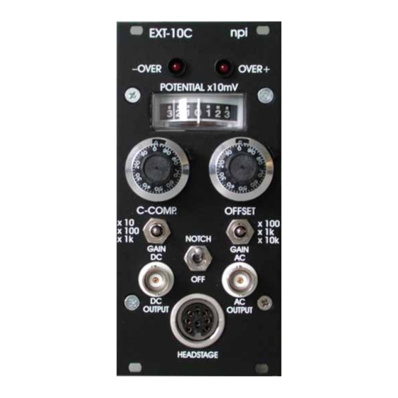
3.4. Description of the Front Panel Figure 2: EXT-10C front panel view In the following description of the front panel elements each element has a number that is related to that in Figure 2. The number is followed by the name (in uppercase letters) written on the front panel and the type of the element (in lowercase letters). - Page 8 EXT-10C User Manual ___________________________________________________________________________ (3) GAIN DC switch Switch to set the GAIN of the outgoing DC signal. Three GAIN factors are available: x10, x100 or x1k. (4) C-COMP. potentiometer Control for compensation of stray capacities of the microelectrode (10 turn potentiometer, range 0-20 pF).
-
Page 9: Headstage
The drawback is that noise is amplified as well. Therefore, the headstage of the EXT-10C is equipped with a differential input that minimizes noise pick-up. Differential means, that the signal for the amplifier is the difference between the positive (+) (P ) and negative (-) (REF.) input of the... - Page 10 EXT-10C User Manual ___________________________________________________________________________ Figure 4: headstage connections, A: differential measurement, B: single-ended measurement ___________________________________________________________________________ version 1.5 page 10...
-
Page 11: Literature
EXT-10C User Manual ___________________________________________________________________________ 4. Literature Barmashenko, G., Eysel, U. T., & Mittmann, T. (2003). Changes in intracellular calcium transients and LTP in the surround of visual cortex lesions in rats. Brain Res. 990, 120- 128. Boulton, A. A., Baker, G. B. & Vanderwolf, C. H. (eds.) (1990). Neurophysiological Techniques, Basic Methods and Concepts. -
Page 12: Technical Data
EXT-10C User Manual ___________________________________________________________________________ 5. Technical Data CMR >90 dB at 1 kHz (tested with 0 Ω input resistance) Differential Input: Ω, range ±1 V Input resistance: >10 Output DC: selectable gain (x10, x100, x1k) Output range: ±12 V into 1 kΩ / ±1 V into 50 Ω load...
Need help?
Do you have a question about the EXT-10C and is the answer not in the manual?
Questions and answers