Table of Contents
Advertisement
Quick Links
OPERATING INSTRUCTIONS AND
SYSTEM DESCRIPTION FOR THE
EXT-02F
EXTRACELLULAR AMPLIFIER
WITH FILTERS
One or Two Channel Recordings
VERSION 4.2
npi 2015
npi electronic GmbH, Bauhofring 16, D-71732 Tamm, Germany
Phone +49 (0)7141-9730230; Fax: +49 (0)7141-9730240
support@npielectronic.com; http://www.npielectronic.com
Advertisement
Table of Contents

Related Manuals for NPI EXT-02F


Summary of Contents for NPI EXT-02F
- Page 1 OPERATING INSTRUCTIONS AND SYSTEM DESCRIPTION FOR THE EXT-02F EXTRACELLULAR AMPLIFIER WITH FILTERS One or Two Channel Recordings VERSION 4.2 npi 2015 npi electronic GmbH, Bauhofring 16, D-71732 Tamm, Germany Phone +49 (0)7141-9730230; Fax: +49 (0)7141-9730240 support@npielectronic.com; http://www.npielectronic.com...
-
Page 2: Table Of Contents
EXT-02F User Manual Table of Contents 1. Safety Regulations ......................3 2. EXT-02F ..........................4 2.1. Components ......................... 4 2.2. System Description ...................... 4 2.3. Description of the Front Panel ..................4 2.4. Description of the Rear Panel ..................8 2.5. -
Page 3: Safety Regulations
VERY IMPORTANT: Instruments and components supplied by npi electronic are NOT intended for clinical use or medical purposes (e.g. for diagnosis or treatment of humans), or for any other life-supporting system. npi electronic disclaims any warranties for such purpose. Equipment supplied by npi electronic must be operated only by selected, trained and adequately instructed personnel. -
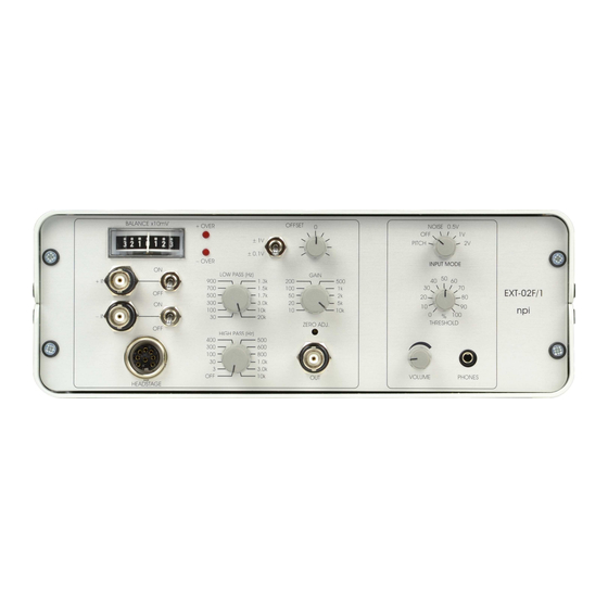
Page 4: Ext-02F
The EXT-02F is designed for extracellular recordings of small voltage signals. The standard model (EXT-02F/2) comprises of two identical channels, but a one channel version (EXT-02F/1) is also available. In the following description of the system only one channel is mentioned, because front panel elements of the two recording channels are identical. - Page 5 (in lowercase letters). Then, a short description of the element is given. Since the front panel elements for the two channel EXT-02F are identical for each channel A and B (with identical functions and labels) these elements are numbered and described only once (for channel A).
- Page 6 Potentiometer for setting the VOLUME of the internal speaker or PHONES linked to connector #9. Turning clockwise will turn up the sound. For EXT-02F/2 two channel amplifier only SOURCE switch Switch for selecting the channel to be monitored (channel A or channel B) ___________________________________________________________________________ version 4.2...
- Page 7 EXT-02F User Manual (12) GAIN switch 10-position switch for selecting the GAIN of the output signal at the OUTPUT connector (#12). Amplification factors: x10, x20, x50, x100, x200, x500, x1k, x2k, x5k, x10k. (13) OUTPUT connector BNC connector providing the recorded and conditioned signal.
-
Page 8: Description Of The Rear Panel
Description of the Rear Panel Figure 2: EXT-02F rear panel view Since the rear panel elements for the two channel EXT-02F are identical for each channel A and B (with identical functions and labels) these elements are numbered and described only once (for channel A). -
Page 9: Headstage (Option)
1 mm or 2 mm banana jacks or using SMC connectors. Very Important: EXT-02F headstages are always labeled “EXT-02” (see Figure 3) and must not be exchanged with headstages from other npi electronic EXT amplifiers, e.g. the modular EXT-10 2F or EXT-10C which are labeled “EXT”! -
Page 10: Operation
EXT-02F User Manual 3. Operation The EXT-02F can be operated either using the inputs of the front panel (#16, Figure 1) or using a headstage. Very Important: You must not use inputs at the front panel and a headstage for one channel simultaneously!! If the BNC connectors are used the headstage must be disconnected. - Page 11 EXT-02F User Manual Figure 4: headstage connections, A: differential measurement, B: single-ended measurement Hint: The REF connector of the headstage can also be set to GND by grounding the –IN connector at the front panel using #14, Figure 1. ___________________________________________________________________________ version 4.2...
-
Page 12: Literature
EXT-02F User Manual 4. Literature Barmashenko, G., Eysel, U. T., & Mittmann, T. (2003). Changes in intracellular calcium transients and LTP in the surround of visual cortex lesions in rats. Brain Res. 990, 120-128. Boulton, A. A., Baker, G. B. & Vanderwolf, C. H. (eds.) (1990). Neurophysiological Techniques, Basic Methods and Concepts. -
Page 13: Technical Data
EXT-02F User Manual 5. Technical Data Ω, range ±1 V Input (BNC connectors): 10 Ω, range ±1 V Input (headstage): >10 CMR >90 dB at 1 kHz (tested with 0 Ω input resistance) Differential Input: Input Capacitance: 30 pF OFFSET compensation: set by potentiometer, range: ±0.1, ±1 V set by toggle switch...
Need help?
Do you have a question about the EXT-02F and is the answer not in the manual?
Questions and answers