Table of Contents
Advertisement
Quick Links
Advertisement
Table of Contents

Related Manuals for NPI BA-01X


Summary of Contents for NPI BA-01X
- Page 1 OPERATING INSTRUCTIONS AND SYSTEM DESCRIPTION FOR THE BA-01X INTRACELLULAR BRIDGE MODE AMPLIFIER VERSION 1.9 npi 2014 npi electronic GmbH, Bauhofring 16, D-71732 Tamm, Germany Phone +49 (0)7141-9730230; Fax: +49 (0)7141-9730240 support@npielectronic.com; http://www.npielectronic.com...
-
Page 2: Table Of Contents
3.3. Description of the Rear Panel ..................15 4. Headstage ..........................16 4.1. Headstage Elements ..................... 16 5. Setting up the BA-01X ....................... 17 6. Passive Cell Model ......................18 6.1. Cell Model Description ....................18 6.2. Connections and Operation ..................19 7. -
Page 3: About This Manual
BA-01X User Manual _________________________________________________________________________________________________________________ About this Manual This manual should help to setup and use the BA-01X system correctly and to perform reliable experiments. If you are not familiar with the use of instruments for intracellular recording of electrical signals please read the manual completely. The experienced user should read at least chapters, 1, 3, 3.3, 0 and 7. -
Page 4: Safety Regulations
VERY IMPORTANT: Instruments and components supplied by npi electronic are NOT intended for clinical use or medical purposes (e.g. for diagnosis or treatment of humans), or for any other life-supporting system. npi electronic disclaims any warranties for such purpose. Equipment supplied by npi electronic must be operated only by selected, trained and adequately instructed personnel. -
Page 5: Ba-01X Components
Other configurations are available, e.g. if the BA-01X system is used only for whole cell patch clamp recordings with suction electrodes the BA-01X system can be delivered with adapted calibrations and a low noise / low bias current headstage (see Optional accessories in chapter 2). -
Page 6: Description Of The Front Panel
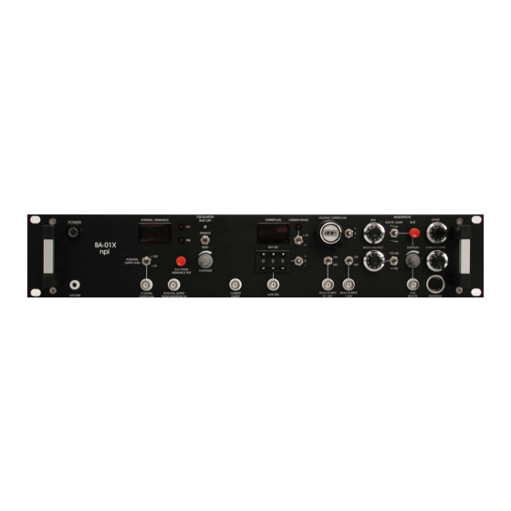
BA-01X User Manual _________________________________________________________________________________________________________________ The system consists of standard desktop cabinet and a headstage which should be placed close to the recording site. The recording electrode is connected to the headstage via an electrode holder (see also Figure 6). In some setups there is no space for placing the headstage very close to the recording site. - Page 7 BA-01X User Manual _________________________________________________________________________________________________________________ Figure 1: BA-01X front panel view (the numbers are related to those in the text below) ___________________________________________________________________________ version 1.9 page 7...
- Page 8 BA-01X User Manual _________________________________________________________________________________________________________________ (1) POWER pressure switch Switch to turn POWER on (switch pushed) or off (switch released). (2) POTENTIAL / RESISTANCE display Display for the recorded potential in mV (XXX mV) or the electrode resistance in MΩ (XXX MΩ, i.e. 100 correspond to 100 MΩ), selected by push button (31).
- Page 9 (10) CURRENT RANGE switch. (9) CURRENT RANGE LED LED indicating the actual current range of the amplifier. LED ON: BA-01X is in x10 range LED OFF: BA-01X is in x1 range (10) CURRENT RANGE switch Switch for setting the current range of the amplifier: x1: max. ±12 nA into 1 GΩ, x10: max.
- Page 10 BNC cable. The duration of the BUZZ is dependent on the setting of the BUZZ DURATION potentiometer (19). potential (mV) 12000 8000 4000 -4000 -8000 start stop -12000 time (ms) Figure 2: buzz function of the BA-01X ___________________________________________________________________________ version 1.9 page 10...
- Page 11 BA-01X User Manual _________________________________________________________________________________________________________________ (16) OFFSET potentiometer Control to set the output of the electrode preamplifier to zero (ten-turn potentiometer, symmetrical, i.e. 0 mV = 5 on the dial), range: ±200 mV (see chapter 7.2). (17) CAPACITY COMP. potentiometer Control for compensation of the input capacitance (ten turn potentiometer, clockwise, range: 0-30 pF, see chapter 7.3).
- Page 12 BA-01X User Manual _________________________________________________________________________________________________________________ CURRENT INPUT unit The CURRENT INPUT unit consists of (23) (25) on / off switches, (24) 1 nA/V connector and (26) 0.1 nA/V connector. (23) on / off switch Switch to enable (on) or disable (off) CURRENT INPUT via 1 nA/V connector.
- Page 13 BA-01X User Manual _________________________________________________________________________________________________________________ gated stimulus unit The gated stimulus unit consists of (7) STEP SIZE digital potentiometer, (27) + / 0 / - switch (STEP SIZE switch) and (28) GATE (TTL) connector. (7) STEP SIZE digital potentiometer Digital potentiometer to set the amplitude of the gated stimulus.
- Page 14 OFFSET, BRIDGE BALANCE etc. (see also Important note below). Caution: When the ELECTRODE RESISTANCE push button is pressed, the BA-01X automatically applies current pulses of ±1 nA to the electrode. Therefore, it should not be used during recordings from cells since this current may stimulate or damage the cell.
-
Page 15: Description Of The Rear Panel
BA-01X User Manual _________________________________________________________________________________________________________________ 3.3. Description of the Rear Panel Figure 5: BA-01X rear panel view (the numbers are related to those in the text below) Mains connector Plug for connecting the BA-01X to mains. Voltage SELECTOR Rotary switch for selecting the mains voltage (110 V-120 V / 220 V-240 V). -
Page 16: Headstage
_________________________________________________________________________________________________________________ 4. Headstage The BA-01X comes with the standard headstage (range: ±12 nA, voltage range x1 or ±120 nA, voltage range x10) for connecting glass electrodes with high resistances or suction electrodes for whole cell patch clamp recordings with lower resistances via an electrode holder (see Figure 6). -
Page 17: Setting Up The Ba-01X
_________________________________________________________________________________________________________________ 5. Setting up the BA-01X The following steps should help you set up the BA-01X correctly. Always adhere to the appropriate safety measures (see chapter 1). After unpacking, the BA-01X is attached to the setup by assembling the electrical connections. -
Page 18: Passive Cell Model
_________________________________________________________________________________________________________________ 6. Passive Cell Model The BA-01X can be ordered with a passive cell model as an optional accessory. An active cell model is also available by request (for ref. see Draguhn et al. (1997)). The passive cell model is designed for use with single electrode amplifiers (BA series, ELC series) to check the function of the instrument in the following circumstances: 1. -
Page 19: Connections And Operation
BA-01X User Manual _________________________________________________________________________________________________________________ Figure 8: Schematic diagram of the passive cell model 6.2. Connections and Operation It is assumed that all connections are built as described in chapter 5. Checking the configuration o Turn POWER switch of the amplifier off. - Page 20 BA-01X User Manual _________________________________________________________________________________________________________________ For a) and b) o Connect GND of the cell model to GND of the headstage. Important: When using the differential headstage (optional) the REF connector must not be left open. It must be connected to ground.
-
Page 21: Test And Tuning Procedures
BA-01X User Manual _________________________________________________________________________________________________________________ 7. Test and Tuning Procedures Important: The BA-01X should be used only in warmed-up condition, i.e. 20 to 30 minutes after turning power on. The following test and tuning procedures are necessary for optimal recordings. It is recommended to first connect a cell model to the amplifier to perform some basic adjustments and to get familiar with these procedures. -
Page 22: Offset Compensation
Figure 9 illustrates the capacitance compensation procedure using a 100 MΩ resistor that represents the electrode. The pulses were generated using the automated electrode resistance test circuit of the BA-01X. The upper diagram shows an undercompensated capacitance. In the diagram in the middle the capacitance is slightly overcompensated and in the lower diagram it is well compensated. - Page 23 BA-01X User Manual _________________________________________________________________________________________________________________ Important: The capacity compensation for the electrode does NOT work if the oscillation shut-off circuit is activated. This may lead to an incorrect reading of the electrode resistance (see also 31) especially when electrodes with high resistances are used.
-
Page 24: Bridge Balance
BA-01X User Manual _________________________________________________________________________________________________________________ 7.4. Bridge Balance If current is passed through an electrode the occurring voltage deflection (potential drop at ) affects the recording of membrane potential. Therefore, this deflection must be compensated carefully by means of the BRIDGE BALANCE control. This control is calibrated in MΩ... - Page 25 BA-01X User Manual _________________________________________________________________________________________________________________ Sometimes the performance of electrodes can be improved by breaking the tip or by using the BUZZ or ELECTRODE CLEAR facilities of the amplifier. Figure 10: Tuning of the BRIDGE BALANCE using 100 MΩ resistor ___________________________________________________________________________ version 1.9...
-
Page 26: Sample Experiments
GND at the headstage. o Make the basic settings (see chapter 0). Again: It is of major importance that the BA-01X systems are used only in warmed-up condition, i.e. 30 minutes after turning power on. - Page 27 BA-01X User Manual _________________________________________________________________________________________________________________ overcompensating the electrode capacitance in several positions of the THRESHOLD potentiometer. o Now the system is preadjusted for measurements. Find a cell! o Approach the desired cell. There are several indications that the electrode is very close to...
- Page 28 BA-01X User Manual _________________________________________________________________________________________________________________ Figure 13: Artifacts caused by the recording electrode. The measurements were done using a cell model with 100 MΩ membrane resistance, 100 pF membrane capacitance and 100 MΩ electrode resistance. A: C and V not compensated (bridge not balanced)
-
Page 29: Sample Experiment Using A Suction (Patch) Electrode
BA-01X User Manual _________________________________________________________________________________________________________________ 8.2. Sample Experiment using a Suction (Patch) Electrode If suction (patch) electrodes are used for whole cell recordings they are usually called “pipettes”. Thus, in this subchapter “pipette” means “suction electrode”. Figure 14: Model circuit for whole cell patch clamp recording using a suction electrode... - Page 30 BA-01X User Manual _________________________________________________________________________________________________________________ Figure 15: Approaching the cell, forming a gigaseal and establishing the whole cell configuration ___________________________________________________________________________ version 1.9 page 30...
-
Page 31: Trouble Shooting
BA-01X User Manual _________________________________________________________________________________________________________________ 9. Trouble Shooting In the following section some common problems, possible reasons and their solutions are described. Important: Please note that the suggestions for solving the problems are only hints and may not work. In a complex setup it is impossible to analyze problems without knowing details. In... -
Page 32: Literature
BA-01X User Manual _________________________________________________________________________________________________________________ Problem 5: The amplifier does not provide any current. Possible reason: 1. The OSCILLATION SHUT OFF circuit is on (LED #30, Figure 1 is red) Solution: 1. Turn the CAPACITY COMP. potentiometer (#17, Figure 1) to the most left position and compensate the input capacitance again. - Page 33 BA-01X User Manual _________________________________________________________________________________________________________________ o Ogden DC (1994) Microelectrode Techniques. The Plymouth Workshop Handbook, Second Edition, The Company of Biologists Limited, Cambridge o Prinz, A. A. and P. Fromherz (2000). Electrical synapses by guided growth of cultured neurons from the snail Lymnaea stagnalis, Biol. Cybern. 82, L1-L5 o Prinz, A.
- Page 34 BA-01X User Manual _________________________________________________________________________________________________________________ o Rathenberg, J., Nevian, T. & Witzemann, V. (2003). High-efficiency transfection of individual neurons using modified electrophysiology techniques. J Neurosci.Methods. 126, 91-98. o Roberts, W. M., & Almers, W. (1992). Patch Voltage Clamping with Low-Resistance Seals: Loose Patch Clamp. In: Rudy, B. & Iversen, L. E. (eds.). Ion Channels. Methods in Enzymology 207, Academic Press San Diego.
-
Page 35: Technical Data
BA-01X User Manual _________________________________________________________________________________________________________________ Technical Data Headstage: Input voltage range: ±1000 mV Operating voltage: ±15 V Enclosure: Size: 23 x 70 x 26 mm, grounded Size: length 150 mm, ∅ 8 mm Holding bar: Electrode connector: BNC with driven shield Ground connector: 2.4 mm connector... - Page 36 BA-01X User Manual _________________________________________________________________________________________________________________ Displays: Potential: XXXX mV (max. 1999 mV) Electrode resistance: XXXX MΩ (max. 1999 MΩ) Current x1: XX.XX nA Current x10: XXX.X nA Inputs: Current stimulus input via BNC connectors, sensitivity dependent on preset CURRENT RANGE 1 nA / V or 0.1 nA / V...
-
Page 37: Index
BA-01X User Manual _________________________________________________________________________________________________________________ Index abbreviations 3 general description 5 accessories 5 GROUND connector 14 basic settings 17 headstage 16 bias current 31 elements 16 bias current adjustment 21 HEADSTAGE connector 11 BIAS current potentiometer 10 HOLDING CURRENT unit 9...
Need help?
Do you have a question about the BA-01X and is the answer not in the manual?
Questions and answers