Table of Contents
Advertisement
Quick Links
Advertisement
Table of Contents

Subscribe to Our Youtube Channel
Related Manuals for NPI TEC-B-01


Summary of Contents for NPI TEC-B-01
- Page 1 OPERATING INSTRUCTIONS AND SYSTEM DESCRIPTION FOR THE TEC-B-01 VOLTAGE CLAMP UNIT FOR BRIDGE AMPLIFIERS VERSION 1.1 npi 2014 npi electronic GmbH, Bauhofring 16, D-71732 Tamm, Germany Phone +49 (0)7141-9730230; Fax: +49 (0)7141-9730240 support@npielectronic.com; http://www.npielectronic.com...
-
Page 2: Table Of Contents
System Description ...................... 4 2.3. Description of the Front Panel ..................4 Current Headstage Bias Current Adjustment for TEC-B-01 ........7 Tuning procedure: ......................7 2.4. Description of the Rear Panel ..................9 ... -
Page 3: Safety Regulations
(e.g. for diagnosis or treatment of humans), or for any other life-supporting system. npi electronic disclaims any warranties for such purpose. Equipment supplied by npi electronic must be operated only by selected, trained and adequately instructed personnel. For details please consult the GENERAL TERMS OF DELIVERY AND CONDITIONS OF BUSINESS of npi electronic, D-71732 Tamm, Germany. -
Page 4: Tec-B-01
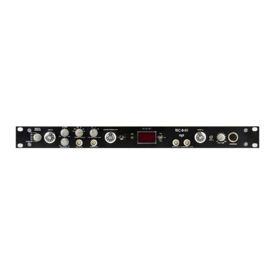
BA-01X or BA-03X. For operation of the bridge amplifier using only one electrode, the MODE OF OPERATION switch of the TEC-B-01 has to be set into EXT or OFF position. In EXT position the TEC-B-01 can be used as current pump, e.g. for iontophoresis. - Page 5 TEC-B-01 User Manual ____________________________________________________________________________________________________________________________ Figure 1: front panel view of the TEC-B-01 __________________________________________________________________________________ version 1.1 page 5...
- Page 6 Current Clamp with current injection through the current headstage Note: In CC operation the current stimulus input of the bridge amplifier is used! EXT.: EXTernal control. For operating the TEC-B-01 amplifier as a constant current source, e.g. for iontophoresis, or for operating the bridge amplifier as stand-alone device...
-
Page 7: Current Headstage Bias Current Adjustment For Tec-B-01
TEC-BA system. The TEC-B-01 is equipped with a current source that is connected to the current injecting electrode and performs the current injection. This current source has a high-impedance floating output. - Page 8 EXT IN 1 µA/V connector (16) BNC connector for connecting an external voltage signal. This can be used to operate the TEC-B-01 module as a constant current source, e.g. for iontophoresis. Scaling is 1 µA / V, i.e. 100 mV connected at EXT IN leads to a current of 100 nA at the current electrode.
-
Page 9: Description Of The Rear Panel
(proportional-integral) system. Time constant range is 10…0.1 ms. 2.4. Description of the Rear Panel A cable is firmly connected for linking the TEC-B-01 amplifier to the bridge amplifier connector TO TEC-B-01 at the rear panel of the bridge amplifier. CHASSIS This connector is linked to mains ground (green / yellow wire, protective earth). -
Page 10: Operation With Bridge Amplifier
(TEVC) or two electrode current clamp (TECC) experiments. The scaling is adapted for current ranges normally used in experiments with oocytes. Figure 3: Rear panel connector of the BA-03X for connection with TEC-B-01 (left). A DUAL LED on the front panel of the BA-03X indicates two electrode operation (right). -
Page 11: Simple Cell Model
ON = C inside the cell, GND = C connected to ground (see also chapter 0) SUBCLICK: SMC connector for the current electrode, resistance: 1 M (built as BNC connector for TEC-B-01). __________________________________________________________________________________ version 1.1 page 11... -
Page 12: Basic Settings
TEC-B-01 User Manual ____________________________________________________________________________________________________________________________ Figure 5: schematic diagram of the TEC passive cell model. For TEC-B-01, there is no REF connector and R = 0 Ω. bath 4.2. Basic settings Before using the TEC-B-01 always make the basic settings to avoid oscillations. -
Page 13: Connections And Operation
5.5). 5. Test and Tuning Procedures Important: The TEC-B-01 and BA amplifiers should be used only in warmed-up condition, i.e. 20 to 30 minutes after turning power on. The following test and tuning procedures are necessary for optimal recordings. It is recommended first to connect a cell model to the amplifier to perform some basic adjustments and to get familiar with these procedures. - Page 14 TEC-B-01 User Manual ____________________________________________________________________________________________________________________________ If the headstage generates an output current, this current will cause a voltage deflection at a test resistor. If this test resistor has a low resistance of only a few k this voltage deflection is nearly zero, and a possible reading at the digital display originates only from a possible offset of the electrode, which can be cancelled using the (CURRENT ELECTRODE) OFFSET (#11) potentiometer.
-
Page 15: Offset Compensation
Therefore, a resistance measurement test for the CURRENT ELECTRODE microelectrodes is included in the TEC-B-01. The respective test for the POTENTIAL ELECTRODE is included in the BA-03X. The test operates independently of any other adjustments, assuming that all microelectrodes are in contact with a grounded bath (zero potential). -
Page 16: Potential Electrode (Ba-03X)
CAPACITY COMPENSATION. The tuning of the capacity compensation control is performed using pulses applied to the COMMAND INPUT or pulses provided by the electrode resistance test circuit. The TEC-B-01 has to be in CC mode (see chapter 5.5). -
Page 17: Testing Operation Modes
That allows measurement of ion fluxes across the cell membrane. This is the most complex mode of operation with the TEC-B-01. Special precautions must be taken while tuning the control circuit in order avoid stability problems. -
Page 18: Tuning The Vc Mode
THRESHOLD potentiometer set to a low value, but not to the most left position) Set the TEC-B-01 amplifier with the MODE OF OPERATION switch (#1) to VC mode. The BA-03X POTENTIAL display should show the holding potential of –50 mV and the TEC- B-01 display (I ) the holding current of –5 µA (according to Ohm's law). -
Page 19: General Considerations
TEC-B-01 User Manual ____________________________________________________________________________________________________________________________ General Considerations The key to accurate and fast recording is a properly built setup. Make sure that the internal system ground is connected to only one point on the measuring ground and originates from the potential headstage. Multiple grounding should be avoided; all ground points should originate from a central point. -
Page 20: Tuning Procedure
TEC-B-01 User Manual ____________________________________________________________________________________________________________________________ Tuning Procedure Before you switch to VC mode tune all parameters related to the recording electrodes (offset, capacity compensation etc.) in CC mode, set GAIN to a low, save level and the control mode switch to NORMAL, GAIN ONLY (see chapter 5.5). Activate the OSCILLATION SHUTOFF unit! ... - Page 21 0). Note: With a standard cell model described in chapter 4 you cannot verify the advantages of the FAST mode (because no series resistance is simulated). Ask npi for a modified cell model with series resistance simulation. Details of how to tune PI controllers and some theoretical aspects are described in chapter 9.2.
-
Page 22: Positioning Of Electrodes
TEC-B-01 User Manual ____________________________________________________________________________________________________________________________ 6. Positioning of Electrodes The position of the electrodes plays an important role in tuning the clamp speed. The position of the current electrode is especially crucial for homogeneous charging of the membrane capacitance, one limiting factor of clamp speed. If the current electrode is placed just at the edge of the oocyte, i.e. with a small penetration depth, the part of the membrane close to the electrode will be charged more quickly than the membrane at the other side of the oocyte. -
Page 23: Sample Experiment
TEC-B-01 User Manual ____________________________________________________________________________________________________________________________ 7. Sample Experiment In the following the basics of a simple experiment are described. It is assumed that all connections are built as described in chapter 4.3. Before starting remove the cell model. Again: It is of major importance that the TEC-03X systems are used only in warmed-up condition i.e. - Page 24 TEC-B-01 User Manual ____________________________________________________________________________________________________________________________ Compensate the potential offset (for both electrodes, see chapter 5.2), measure the electrode resistance (for both electrodes, see chapter 5.3). The resistances should be 700 k to 1-2 M for the potential electrode and 500 k to 1 M for the current electrode. As mentioned above, it is usually not necessary to compensate for the electrode capacity (for the potential electrode, see chapter 5.4).
-
Page 25: Trouble Shooting
TEC-B-01 User Manual ____________________________________________________________________________________________________________________________ 8. Trouble Shooting In the following section some common problems, possible reasons and their solutions are described. Important: Please note that the suggestions for solving the problems are only hints and may not work. In a complex setup it is impossible to analyze problems without knowing details. In case of trouble always contact an experienced electrophysiologist in your laboratory if possible and connect a cell model to see whether the problem occurring with electrodes and “real”... -
Page 26: Appendix
TEC-B-01 User Manual ____________________________________________________________________________________________________________________________ 9. Appendix 9.1. Theory of Operation The standard configuration for voltage clamping oocytes is the two electrode voltage clamp arrangement (Stühmer, 1992; Stühmer et al. 1992; Dietzel et al., 1992; Stühmer, 1998). In contrast to previously described clamp systems (for review see Smith et al., 1985) the amplifiers for oocyte clamping must meet special requirements since oocytes are very large cells with a high membrane capacity (up to 100-500 nF) and large membrane currents (up to 100 µA and more). - Page 27 TEC-B-01 User Manual ____________________________________________________________________________________________________________________________ the "large" time constant determines the maximum gain which can be achieved without oscillations and thus, the accuracy of the clamp. With the gain adjusted to this level the integrator time constant and "small" time constant determine the speed of response of the system.
-
Page 28: Tuning Procedures For Vc Controllers
TEC-B-01 User Manual ____________________________________________________________________________________________________________________________ 9.2. Tuning Procedures for VC Controllers The initial settings (see voltage clamp in chapter 5.5) guarantee only a stable clamp that is not very accurate and insufficiently rapid for certain types of experiments, e.g. investigation of fast voltage- activated ion channels or gating currents. - Page 29 TEC-B-01 User Manual ____________________________________________________________________________________________________________________________ Very important: All parameters that influence clamp performance (microelectrode offsets, capacity compensation, etc.) must be optimally tuned before starting the PI controller tuning procedure (see chapter 5). Always activate the OSCILLATION SHUTOFF unit. The tuning procedure involves the following steps: Again: The main criterion of tuning is the amount of overshoot seen at the potential output.
- Page 30 TEC-B-01 User Manual ____________________________________________________________________________________________________________________________ Since SERIES RESISTANCE COMPENSATION is done by positive feedback in the control circuit, its use can lead very quickly to stability problems. Therefore, the clamp speed should be improved first through conventional methods. The optimal positioning of the electrodes, especially of the current electrode is important for best SERIES RESISTANCE COMPENSATION (see also chapter 0).
-
Page 31: Speed Of Response And Linearity Of The Capacitive Transients
TEC-B-01 User Manual ____________________________________________________________________________________________________________________________ 9.3. Speed of Response and Linearity of the Capacitive Transients For the investigation of voltage activated channels with voltage clamp instruments, some special techniques for eliminating the capacitive and leak currents have been introduced, such as the P/4 or more general P/N protocol (see Rudy and Iverson, 1992 for overview). - Page 32 TEC-B-01 User Manual ____________________________________________________________________________________________________________________________ The proportional gain of the clamp system can be calculated as follows (Froehr, 1985; Polder, 1984): K = C / 4 * T Linear optimum (LO), aperiodic response, no overshoot K = C / 2 * T Modulus optimum (MO or AVO, respectively), 4% overshoot, fastest rise time The optimal gain for a VC experiment is in between these two values.
- Page 33 TEC-B-01 User Manual ____________________________________________________________________________________________________________________________ The speed of response (with x1 headstage and 150 V output) from the point of view of control theory = 94 µs = 168 µs Maximum speed of response The speed of an ideal VC system is limited only by the maximum current delivered by the current...
-
Page 34: Technical Data
TEC-B-01 User Manual ____________________________________________________________________________________________________________________________ Technical Data Modes of Operation Current Clamp mode Voltage Clamp mode OFF: Current- and Voltage Clamp disabled, BA amplifier operational EXT: External mode MODE selection: by rotary switch __________________________________________________________________________________ version 1.1 page 34... - Page 35 TEC-B-01 User Manual ____________________________________________________________________________________________________________________________ Headstages Potential headstage Bridge amplifier headstage is used for potential measurement Current headstage Operating voltage: ±45 V Input resistance: >10 Electrode connector: BNC, shield is grounded Ground: 2.4 mm connector or headstage enclosure Size: 23 x 70 x 26 mm, enclosure grounded...
Need help?
Do you have a question about the TEC-B-01 and is the answer not in the manual?
Questions and answers