Table of Contents
Advertisement
Quick Links
OPERATING INSTRUCTIONS AND
SYSTEM DESCRIPTION FOR THE
ELC-01MX
ELC AMPLIFIER MODULE
for EXTRA & INTRACELLULAR RECORDING,
SINGLE CELL STIMULATION and
ELECTROPORATION
VERSION 2.6
npi 2015
npi electronic GmbH, Bauhofring 16, D-71732 Tamm, Germany
Phone +49 (0)7141-9730230; Fax: +49 (0)7141-9730240
support@npielectronic.com; http://www.npielectronic.com
Advertisement
Table of Contents

Related Manuals for NPI ELC-01MX


Summary of Contents for NPI ELC-01MX
- Page 1 OPERATING INSTRUCTIONS AND SYSTEM DESCRIPTION FOR THE ELC-01MX ELC AMPLIFIER MODULE for EXTRA & INTRACELLULAR RECORDING, SINGLE CELL STIMULATION and ELECTROPORATION VERSION 2.6 npi 2015 npi electronic GmbH, Bauhofring 16, D-71732 Tamm, Germany Phone +49 (0)7141-9730230; Fax: +49 (0)7141-9730240 support@npielectronic.com; http://www.npielectronic.com...
-
Page 2: Table Of Contents
2.8.3 EPMS-E-07 ....................6 2.8.4 EPMS-03 ....................... 6 3 Rationale ..........................7 4 ELC-01MX ......................... 9 4.1 ELC-01MX Components ..................... 9 4.2 Optional Accessories ....................9 4.3 System Description ...................... 9 4.3.1 Operation modes of the amplifier ..............9 4.3.2 Input configuration:.................. -
Page 3: Safety Regulations
VERY IMPORTANT: Instruments and components supplied by npi electronic are NOT intended for clinical use or medical purposes (e.g. for diagnosis or treatment of humans), or for any other life-supporting system. npi electronic disclaims any warranties for such purpose. Equipment supplied by npi electronic must be operated only by selected, trained and adequately instructed personnel. -
Page 4: Epms-07 Modular Plug-In System
2 EPMS-07 Modular Plug-In System General System Description / Operation The npi EPMS-07 is a modular system for processing of bioelectrical signals in electrophysiology. The system is housed in a 19” rack-mount cabinet (3U) has room for up to 7 plug-in units. The plug-in units are connected to power by a bus at the rear panel. -
Page 5: Epms-03
Note: The chassis of the PWR-03D is connected to protective earth, and it provides protective earth to the EPMS-E housing if connected. Figure 3: Left: PWR-03D front panel view Right: PWR-03D rear panel view. Note: This power supply is intended to be used with npi EPMS-E systems only. version 2.6 page 5... -
Page 6: System Grounding
ELC-01MX User Manual System Grounding 2.7.1 EPMS-07/EPMS-03 The 19" cabinet is grounded by the power cable through the ground pin of the mains connector (= protective earth). In order to avoid ground loops the internal ground is isolated from the protective earth. The internal ground is used on the BNC connectors or GROUND plugs of the modules that are inserted into the EPMS-07 housing. -
Page 7: Rationale
ELC-01MX User Manual 3 Rationale “Loose patch” recordings (or “loose seal” recordings [Roberts & Almers, 1992]) are used to record from single excitable cells without damage, i.e. without a direct access to the cell interior. This technique was described in a seminal paper, “A method has been developed... - Page 8 ELC-01MX User Manual Today three methods are used to record electrically in vivo or in vitro: Recordings using patch (suction) electrode from single neurons Whole-cell patch clamp technique (tight seal recording, intracellular) Loose patch technique (loose seal recording, extracellular) Intracellular recordings with sharp microelectrodes...
-
Page 9: Elc-01Mx
The system consists of a module for the npi EPMS-07 modular system and a small headstage with holding bar, dovetail or a mounting plate. It can be used in slices or in in vivo preparations using the optional headstage with a differential input or for recordings in free moving animals using a miniature headstage. -
Page 10: Input Configuration
TTL signal connected to the MODE SELECT BNC (LO = CC, HI = VC). 4.3.4 Output configuration The ELC-01MX amplifier has two output BNC connectors for POTENTIAL and one output BNC for the CURRENT signal. The POTENTIAL OUTPUT x1 is a pure DC output that monitors the electrode potential. -
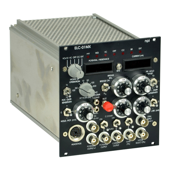
Page 11: Description Of The Front Panel
ELC-01MX User Manual 4.4 Description of the Front Panel Figure 5: ELC-01MX front panel view In the following description of the front panel elements each element has a number that is related to that in Figure 5. The number is followed by the name (in uppercase letters) written on the front panel and the type of the element (in lowercase letters). - Page 12 ELC-01MX User Manual (2) PIP. HOLD / OFFSET potentiometer Control to compensate for the electrode potential OFFSET (ten-turn potentiometer, symmetrical, i.e. 0 mV = 5 on the dial) in CC mode (range: ±100 mV), or to zero the pipette current in VC mode.
- Page 13 ELC-01MX User Manual (8) MODE SELECT (TTL) connector BNC connector for remote control of the MODE of operation. The TTL signal connected here selects the mode of operation remotely (HI = VC, LO = CC); functional in EXT mode only.
- Page 14 ELC-01MX User Manual (14) COMM. INP. ÷10 mV connector Please see below (Voltage Clamp Unit) (15) HEADSTAGE connector Connector to attach the HEADSTAGE via a flexible cable. Voltage Clamp Unit The voltage clamp unit consists of (14) COMM. INP. /10 mV connector, (16, 17) AMPL and T.CONST.
- Page 15 ELC-01MX User Manual Extracellular recording unit The extracellular recording unit consist of (20) HP FILTER (Hz) switch and (21) POT. OUTP. SENSITIVITY switch. Hint: Set the MODE OF OPERATION switch to OFF for extracellular low-noise recording. (19) HP FILTER (Hz) switch Switch for setting the corner frequency of the high-pass filter (attenuation: -6 dB/octave) in AC recording mode.
-
Page 16: Headstage
Trim potentiometer for adjusting the output BIAS current of the headstage (see also chapter 5.2). 5 Headstage The ELC-01MX comes with a headstage for connecting suction electrodes for loose-patch clamp or whole cell recordings and / or stimulation or electroporation, respectively, or sharp electrodes for extracellular or intracellular recordings. -
Page 17: Headstage Elements
(for details see Kettenmann and Grantyn (1992)). An automated chlorinating apparatus (ACl-01) is available from npi for optimal chlorinating of sliver wires (please contact npi for details). -
Page 18: Headstage Bias Current Adjustment
Caution: It is important that this tuning procedure is performed ONLY after a warm-up period of at least 30 minutes! The ELC-01MX is equipped with a voltage-to-current converter with a very high output impedance which is connected to the recording electrode. The zero current of this unit is tuned with the BIAS current trim-pot (see #26 in Figure 5). -
Page 19: Passive Cell Model
ELC-01MX User Manual 6 Passive Cell Model The cell model is designed to be used to check the function of the instrument either 1. just after unpacking to see whether the instrument has been damaged during transport or 2. to train personnel in using the instrument or 3. -
Page 20: Connections And Operation
ELC-01MX User Manual 1, 3: connectors for the headstage, 1: electrode resistance: 50 MΩ, 3: electrode resistance: 10 MΩ GND ground connector, to be connected to GND jack of the headstage CELL: switch for cell membrane representing a membrane of either 50 MΩ and 22 pF (CELL 1) or 200 MΩ... - Page 21 ELC-01MX User Manual b) For simulation of an experiment using a sharp electrode Connect the BNC jack labeled 50 MΩ of the cell model to the BNC connector P at the headstage. For a) and b) Connect GND of the cell model to GND of the headstage.
-
Page 22: Introduction Into Experiments
ELC-01MX User Manual 7 Introduction into Experiments The ELC-01MX is capable to perform several types of experiments that are briefly introduced in the following. It is assumed that the capacity of the electrode is compensated, the offset of the electrode is cancelled and, for intracellular recordings in BRIDGE mode, electrode artifact is eliminated using the bridge balance circuit. -
Page 23: Extracellular Voltage Measurement
ELC-01MX User Manual Figure 10: headstage connections, A: differential measurement, B: single-ended measurement 7.2 Extracellular Voltage Measurement Extracellular measurements are usually done in a loose-patch configuration or with special metal microelectrodes. Recordings with extracellular metal electrodes is simple. The electrode is advanced in the region where the recordings will be made using a micromanipulator and the signals are filtered and amplified (see chapter 5 in Lalley et al., 1999 for details). -
Page 24: Extracellular Stimulation And Electroporation
ELC-01MX User Manual 7.3 Extracellular Stimulation and Electroporation Cells can be stimulated using current or voltage signals. 7.3.1 Stimulation with Current Approach the cell in VC mode and apply square voltage pulses to the electrode. Contact the cell, establish the loose-patch and disconnect the voltage signal from COMM. -
Page 25: Intracellular Recording
Apply stimuli to the cell using the STIM. INPUT 10 nA/V BNC connector (#7, Figure 5). 7.4.2 Voltage Clamp Recording The ELC-01MX can also be used like a simple patch-clamp amplifier. Approach the cell in VC mode and apply square voltage pulses to the electrode. -
Page 26: Literature
ELC-01MX User Manual 8 Literature General Recording Methods and Voltage Clamp Technique Dietzel, I. D., Bruns, D., Polder, H. R. and Lux, H. D. (1992). Voltage Clamp Recording, in Kettenmann, H. and R. Grantyn (eds.) Practical Electrophysiological Methods, Wiley- Liss, NY. - Page 27 ELC-01MX User Manual Pinault, D. (1996). A novel single-cell staining procedure performed in vivo under electro- physiological control: morpho-functional features of juxtacellularly labeled thalamic cells and other central neurons with biocytin or Neurobiotin. J Neurosci.Methods. 65, 113-136. Pinault, D. (2011) The Juxtacellular Recording-Labeling Technique, Chapter 4, 41-77 in: Vertes, R.
- Page 28 ELC-01MX User Manual Bhumbra GS, Bannatyne BA, Watanabe M, Todd AJ, Maxwell DJ, Beato M. (2014). The recurrent case for the Renshaw cell. Journal of Neuroscience 34, 12919-32. doi: 10.1523/JNEUROSCI.0199-14.2014. Geis, C., Weishaupt, A., Hallermann, S., Grunewald, B., Wessig, C., Wultsch, T., Reif, A., Byts, N., Beck, M., Jablonka, S., Boettger, M.
- Page 29 ELC-01MX User Manual Lee D, Shtengel G, Osborne JE, Lee AK. (2014). Anesthetized- and awake-patched whole- cell recordings in freely moving rats using UV-cured collar-based electrode stabilization. Nature Protocols 9, 2784-95. doi: 10.1038/nprot.2014.190. In-vivo recording with miniature headstage using ELC amplifiers Epsztein, J., Brecht, M., &...
-
Page 30: Technical Data
ELC-01MX User Manual 9 Technical Data Module for EPMS-07 system with headstage Headstage: Input voltage range: ±12 V Operating voltage: ±15 V Enclosure: Size: 23 x 70 x 26 mm, grounded Headstage connector: 8-pole DIN connector Electrode connector: BNC with driven shield Ground connector: 2.4 mm banana jack... - Page 31 ELC-01MX User Manual Potential output: BNC connector, range: 10, 100, 1000 Potential low-pass filter: 3-pole BESSEL filter (other options available) attenuation: -18 dB/octave, corner frequency: 3 kHz Potential high-pass filter: 1-pole BESSEL filter, other options available, attenuation: -6 dB/octave, corner frequencies...
Need help?
Do you have a question about the ELC-01MX and is the answer not in the manual?
Questions and answers