Advertisement
Quick Links
Advertisement

Related Manuals for NPI ELECTROPORATOR ELP-02D


Summary of Contents for NPI ELECTROPORATOR ELP-02D
- Page 1 OPERATING INSTRUCTIONS AND SYSTEM DESCRIPTION FOR THE ELECTROPORATION AMPLIFIER 100 V / 10 mA max. VERSION 1.0 npi 2020 npi electronic GmbH, Bauhofring 16, D-71732 Tamm, Germany Phone +49 (0)7141-9730230; Fax: +49 (0)7141-9730240 support@npielectronic.com; http://www.npielectronic.com...
-
Page 2: Table Of Contents
ELPORATOR - User Manual _________________________________________________________________________________________________________________ Table of Contents Safety Regulations ......................3 Special Safety Notice for High Voltage Instruments ............4 ELP-02D Electroporator Unit ..................... 5 3.1. System Description ...................... 5 3.2. Description of the Front Panel .................. -
Page 3: Safety Regulations
(e.g. for diagnosis or treatment of humans) or for any other life-supporting system. npi electronic disclaims any warranties for such purpose. Equipment supplied by npi electronic must be operated only by selected, trained and adequately instructed personnel. -
Page 4: Special Safety Notice For High Voltage Instruments
ELPORATOR - User Manual _________________________________________________________________________________________________________________ 2. Special Safety Notice for High Voltage Instruments HIGH VOLTAGE!! RISK OF ELECTROCUTION!! Observe extreme caution when working with this instrument!!! Always connect high voltage power supplies to protective earth!! Do not touch connections unless the instrument is turned off and the capacitance of both the load and power supply are earthed!! Allow adequate time for discharge of internal capacitance of the power supply!! Do not ground yourself or work under wet or damp conditions!! -
Page 5: Elp-02D Electroporator Unit
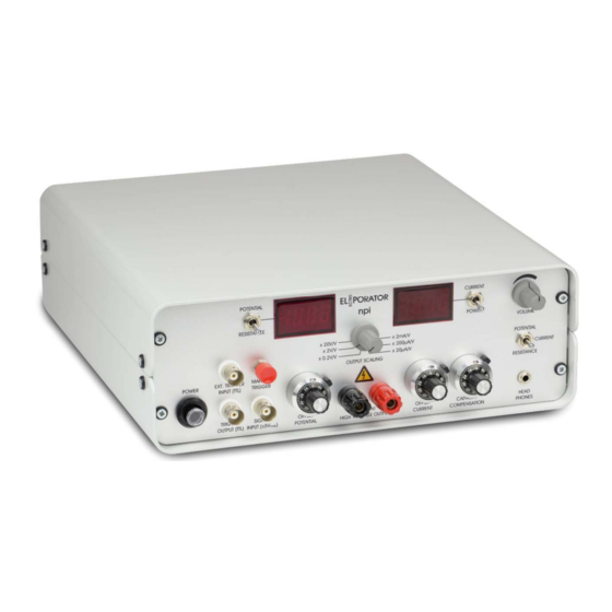
ELPORATOR - User Manual _________________________________________________________________________________________________________________ 3. ELP-02D Electroporator Unit 3.1. System Description The ELectroPORATOR unit is designed for application of voltage and current stimuli for electroporation of cells. The output signal is not isolated from ground and can either be a voltage up to 100 V or a current up to 10 mA. - Page 6 ELPORATOR - User Manual _________________________________________________________________________________________________________________ OUTPUT SCALING rotary switch Rotary switch for selecting how the output signal is scaled relative to the input signal at #16. Voltage output: x 0.2 V/V x 2 V/V x 20 V/V Current output: x 2 mA/V x 200 µA/V x 20 µA/V CURRENT/POWER display...
- Page 7 ELPORATOR - User Manual _________________________________________________________________________________________________________________ (11) OFFSET CURRENT potentiometer Potentiometer compensate for the CURRENT OFFSET of the electroporating electrode. It is recommended to compensate the offsets only in a completely warmed up condition, i.e. after 30 minutes warm-up time (see below). Offset range is dependent on current scaling. See also technical data.
-
Page 8: Description Of The Rear Panel
ELPORATOR - User Manual _________________________________________________________________________________________________________________ 3.3. Description of the Rear Panel Figure 2: ELectroPORATOR rear panel view MONITORING OUTPUT connectors (1) POTENTIAL 0.1 V/V connector (2) CURRENT 100/10/1 mV/µA connector (scaling dependent on current scaling) (3) RESISTANCE 1 V/MΩ connector (4) POWER 10 V/W connector (5) REMOTE connector BNC connector with active low logic. -
Page 9: Operation
ELPORATOR - User Manual _________________________________________________________________________________________________________________ (10) Mains connector Plug socket for the mains power-plug. Important: Check line voltage before connecting the ELectroPOATOR to power. Always use a three-wire line cord and a mains power-plug with a protection contact connected to ground. Disconnect mains power-plug when replacing the fuse or changing line voltage. -
Page 10: Technical Data
ELPORATOR - User Manual _________________________________________________________________________________________________________________ 5. Technical Data Output modes: voltage source, current source selectable with rotary switch Scaling: Voltage output: x 0.2 V/V x 2 V/V x 20 V/V Current output: x 2 mA/V x 200 µA/V x 20 µA/V Displays: Potential: XXX.X V... - Page 11 ELPORATOR - User Manual _________________________________________________________________________________________________________________ Input voltage range: ±5 V Output voltage: ±100 V max. Output current: ±10 mA max. Dimensions: 245 x 260 x 90 mm³ ___________________________________________________________________________ version 1.0 page 11...
Need help?
Do you have a question about the ELECTROPORATOR ELP-02D and is the answer not in the manual?
Questions and answers