Table of Contents
Advertisement
Quick Links
OPERATING INSTRUCTIONS AND
SYSTEM DESCRIPTION FOR THE
ELECTROPORATION AMPLIFIER
100 V / 10 mA max. (current + voltage version)
VERSION 1.6
npi 2024
npi electronic GmbH, Bauhofring 16, D-71732 Tamm, Germany
Phone +49 (0)7141-9730230; Fax: +49 (0)7141-9730240
support@npielectronic.com; http://www.npielectronic.com
Advertisement
Table of Contents

Subscribe to Our Youtube Channel
Related Manuals for NPI ELectroPORATOR


Summary of Contents for NPI ELectroPORATOR
- Page 1 OPERATING INSTRUCTIONS AND SYSTEM DESCRIPTION FOR THE ELECTROPORATION AMPLIFIER 100 V / 10 mA max. (current + voltage version) VERSION 1.6 npi 2024 npi electronic GmbH, Bauhofring 16, D-71732 Tamm, Germany Phone +49 (0)7141-9730230; Fax: +49 (0)7141-9730240 support@npielectronic.com; http://www.npielectronic.com...
-
Page 2: Table Of Contents
Table of Contents 1. Safety Regulations ......................3 2. Special Safety Notice for High Voltage Instruments ............4 3. ELP-02D Electroporator Unit ..................... 5 3.1. System Description ...................... 5 3.2. Description of the Front Panel ..................6 3.3. Description of the Rear Panel ..................8 3.4. -
Page 3: Safety Regulations
(e.g. for diagnosis or treatment of humans) or for any other life-supporting system. npi electronic disclaims any warranties for such purpose. Equipment supplied by npi electronic must be operated only by selected, trained and adequately instructed personnel. -
Page 4: Special Safety Notice For High Voltage Instruments
ELectroPORATOR - Manual 2. Special Safety Notice for High Voltage Instruments HIGH VOLTAGE!! RISK OF ELECTROCUTION!! Observe extreme caution when working with this instrument!!! Always connect high voltage power supplies to protective earth!! Do not touch connections unless the instrument is turned off and the capacitance of both... -
Page 5: Elp-02D Electroporator Unit
3. ELP-02D ELectroPORATOR Unit 3.1. System Description The ELectroPORATOR unit is designed for application of voltage pulses for electroporation of cells. The output signal is not isolated from ground and is a voltage up to 100 V with a current up to 10 mA. -
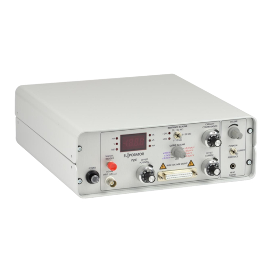
Page 6: Description Of The Front Panel
ELectroPORATOR - Manual 3.2. Description of the Front Panel POWER switch Pushbutton to switch the amplifier ON (pushed) or OFF (released). SIGNAL INPUT (±5 Vmax) connector BNC connector for the input of an analog signal. Please do not exceed ±5 V. - Page 7 ELectroPORATOR - Manual CAPACITY COMPENSATION potentiometer Potentiometer to compensate for the stray capacitances of cables and electrodes in CURRENT output mode. It is recommended to compensate the capacity only in a completely warmed up condition i.e. after 45 to 60 minutes warm-up time. See also chapter 4.3.
-
Page 8: Description Of The Rear Panel
SIGNAL INPUT. (5) OUTPUT TTL BNC connector providing a TTL HIGH signal (length: 1 ms) when the electroporator’s trigger unit is activated. This TTL signal is used for triggering the function generator or data acquisition system. - Page 9 (11) Mains connector Plug socket for the mains power-plug. Important: Check line voltage before connecting the ELectroPORATOR to power. Always use a three-wire line cord and a mains power-plug with a protection contact connected to ground. Disconnect mains power-plug when replacing the fuse or changing line voltage. Replace fuse only by appropriate specified type (one spare fuse is supplied).
-
Page 10: Description Of The Headstage
There is also a capacitor of 100 pF which will be put in parallel to the chosen resistor if the CAPACITOR switch is in ON position. Figure 4: Model cell for the ELectroPORATOR. Version 1.6... -
Page 11: Operation
HIGH VOLTAGE OUTPUT and scaled according to the settings at the OUTPUT SCALING switch. The ELectroPORATOR has a trigger unit for starting the function generator or data acquisition system connected to SIGNAL INPUT. This trigger can be set manually by the MANUAL TRIGGER or a footswitch/button connected to REMOTE LOW ACTIVE TTL at the rear panel. -
Page 12: Approaching Cells In Resistance Mode
ELectroPORATOR - Manual 4.4. Approaching cells in RESISTANCE mode RESISTANCE mode (switch #5) can be used in combination with the audio monitor for approaching cells. When a cell is found and the pipette gets close to its membrane, this can be heard as a change in resistance. -
Page 13: Technical Data
ELectroPORATOR - Manual 5. Technical Data Output modes: Voltage or current source Scaling: For output scaling see table below. Display: See also table below. Potential: OUTPUT SCALING DISPLAY x0.2 V/V XXXX mV x2 V/V XXX.X V x20 V/V XXX.X V... - Page 14 ELectroPORATOR - Manual Offset Ranges: Potential: OUTPUT SCALING POTENTIAL OFFSET range 0.2 V/V ±10 mV 2 V/V ±100 mV 20 V/V ±1 V Current: OUTPUT SCALING CURRENT OFFSET range 0.2 µA/V ±10 nA 2 µA/V ±100 nA 20 µA/V ±1 µA 0.2 mA/V...
Need help?
Do you have a question about the ELectroPORATOR and is the answer not in the manual?
Questions and answers