Table of Contents
Advertisement
Advertisement
Table of Contents
Troubleshooting

Related Manuals for Delta RPI-H3


Summary of Contents for Delta RPI-H3
-
Page 2: Table Of Contents
Contents 1. General Information ..............1 1.1 About this Manual ................1 1.2 Safety Symbol & Instruction..............1 1.3 Validity ....................1 1.4 Product Description ................2 1.5 How It Works ..................2 1.6 Additional Information .................3 2. Installation and Wiring ............4 2.1 Instruction before Installation ..............4 2.2 Unpacking...................4 2.3 Package Inspection ................5 2.4 Identification Label................6... - Page 3 6.1.1 Power Limit ..................20 6.1.2 Power vs. Frequency ..............20 6.2 Reactive Power Control ..............21 6.2.1 Fixed power Factor cosφ(VDE-AR-N 4105,CEI 0-21)....22 6.2.2 cosφ(P) (VDE-AR-N 4105,CEI 0-21) ..........22 6.2.3 Fixed Reactive Power In Var(CEI 0-21) .........22 6.2.4 Reactive Power / Voltage Characteristic Q(U)(CEI 0-21)....23 6.3 Low Voltage Ride Through (LVRT) ...........24 7.
- Page 4 Appendix A : Multi-function Relay ........... 47 A.1 Multi-function relay output connection ..........47 Appendix B : Digital Input............48...
- Page 5 Figure 3-3 Inverter exterior objects ..............8 Figure 3-4 LCD display and control panel............8 Figure 3-5 Input/Output interface ..............9 Figure 4-1 Screw the mounting bracket for RPI-H3 ........11 Figure 4-2 Screw the mounting bracket for RPI-H5 ........12 Figure 4-3 Correct and incorrect installation illustration .........13 Figure 4-4 Proper installation gap ..............14...
- Page 6 Table Index Table 2-1 Packing list ..................5 Table 5-1 AC wire requirement...............16 Table 5-2 Definition of RS-485 ...............19 Table 5-3 RS-485 data format ................19 Table 7-1 Country list ..................32 Table 7-2 Language list..................33 Table 9-1 Measurement and message............37 Table 9-2 Error message................38 Table 11-1 Specifications ................45...
-
Page 7: General Information
This manual provides the detailed information of specification, installation procedures and all related function settings about the solar inverter model- RPI-H3/RPI-H5. Installation technicians must be well-trained and qualified for installing solar system and must follow all the safety instructions and installation procedures. -
Page 8: Product Description
(DC) electricity from photovoltaic power collected from PV Array into single phase alternating current (AC) to feed the excess capacity back to the local main electrical grid. This inverter allows wide voltage input range (125~550VDC for RPI-H3 and 200~1000VDC for RPI-H5) and high performance efficiency based on user’s friendly operation design. -
Page 9: Additional Information
1.6 Additional Information For more detailed information for RPI-H3/RPI-H5 or other related product information, please visit http://www.deltaww.com... -
Page 10: Installation And Wiring
2. Installation and Wiring 2.1 Instruction before Installation Due to variety of users’ installation environment, reading this manual thoroughly before installation is strongly recommended. All the installation and start-up procedures must be undertaken by professional and well-trained technician. 2.2 Unpacking Unpacking process is shown as Figure 2-1. -
Page 11: Package Inspection
Table 2-1: Table 2-1 Packing list RPI-H3/RPI-H5 Object Description PV Inverter 1 3kVA(RPI-H3), 5kVA(RPI-H5) solar inverter The Instruction to provide the information of safety, User Manual Installation, specification, etc. AC Plug 1 Connector for AC connection Wall-Mounting... -
Page 12: Identification Label
2.4 Identification Label Users can identify the model number by the information on the product label. The model number, specifications as well as the series No. is specified on the product label. Regard to the label location, please refer to Figure 2-2. Figure 2-2 The identification label... -
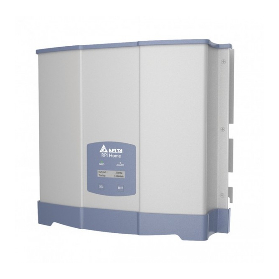
Page 13: Product Overview
3. Product Overview 3.1 Dimension Figure 3-1 Dimension of RPI-H3 Figure 3-2 Dimension of RPI-H5... -
Page 14: Function Introduction
3.2 Function Introduction Inverter’s exterior objects are shown on the Figure 3-3, and the detailed description is in sections 3.2.1 and 3.2.2. Figure 3-3 Inverter exterior objects 3.2.1 LCD Display and Buttons Figure 3-4 LCD display and buttons... -
Page 15: Inverter Input/Output Interface
3.2.2 Inverter Input/Output Interface Figure 3-5 Input/Output interface... -
Page 16: Installation
AC plug at the bottom. Do not install the device on a slanting wall. The dimensions of mounting bracket are shown as figure below. There are 7 pcs(RPI-H3)/12pcs(RPI-H5) of M5 screws required for mounting plate. Fix the supplied wall-mount plate securely on the wall before mounting... - Page 17 Figure 4-1 Screw the mounting bracket for RPI-H3...
- Page 18 Figure 4-2 Screw the mounting bracket for RPI-H5...
- Page 19 Figure 4-3 Correct and incorrect installation illustration CAUTION The location and hardware should be a solid surface or a firm holder that suitable for the weight of inverter. Suggested to install the inverter to the location which offers free and safe access. It would streamline the service and maintenance Please leave an appropriate gap in between when installing singe/ several solar inverter systems.
- Page 20 Ambient temperature -20℃~60℃.(power derating above 40℃) There shall be sufficient space for product operation as shown as the Figure 4-4. If necessary, installer can increase the gap space for sufficient operation space. Figure 4-4 Proper installation gap...
-
Page 21: Wiring
1. Make sure whether the voltage values, polarities are correct. 2. When grounding of the solar array is necessary, an isolation transformer is required due to the RPI-H3/RPI-H5 not having a galvanic isolation between the DC-input and AC-output. 3. The ground fault detection is a fixed internal setting. It always works and can not be modified. -
Page 22: Ac Grid Connection: L + N + Pe
(default), The voltage between each phase and the neutral is 230/220 V. The voltage between two phases is 400/380V. Delta configuration (3 phased wires only) : L–L, The voltage between two phases are 230/220V. As there is no neutral, there is no phase-neutral voltage. -
Page 23: Dc Connection (From Pv Array)
When doing DC wiring, please confirm that PV Array’s power switch is off. CAUTION ! ◆ The maximum open circuit voltage of PV Array must not exceed 550V (RPI-H3) / 1000V (RPI-H5). ◆ The recommended PV power connect to inverter is 3600W... -
Page 24: Communication Module
(RPI-H3) / 5950W (RPI-H5). ◆ The device installed between PV Array and inverter must meet the rating of voltage higher than this device’s maximum input voltage. Cable size: Current Rating Wire size DC 15 A (RPI-H3) DC 17.5 A (RPI-H5) -
Page 25: Rs-485 Connection
5.4.1 RS-485 Connection The pin definition of RS-485 is shown as in Table 5-2 and protocol settings are listed in Table 5-3. The wiring of multi-inverter connection is shown as figure 5-6. . Table 5-2 Definition of RS485 FUNCTION DATA- DATA+ 12 Vdc Figure 5-6 Multi-inverter connection illustration... -
Page 26: Active/Reactive Power Control And Low Voltage Ride
6. Active/Reactive Power Control and Low Voltage Ride Through (Optional) There are 2 settings for active power and 4 settings for reactive power control based on the requirement from network operator. 6.1 Active Power Control 6.1.1 Power Limit Users can reduce inverter output power by set percentage of actual or rated power. -
Page 27: Reactive Power Control
Power vs. frequency curve for VDE-AR-N 4105 Power vs. frequency curve for CEI-021 Figure 6-1 Power vs. frequency characteristic 6.2 Reactive Power Control With active power output, it must be possible to operate the generating plant in any operating point with at least a reactive power output corresponding to a active factor at the network connection point of cos ϕ... -
Page 28: Fixed Power Factor Cosφ(Vde-Ar-N 4105,Cei 0-21)
target value variably adjustable by remote control (or other control technologies) will be specified by the network operator in the transfer station. The setting value is either 1. fixed power factor cosφ (VDE-AR-N 4105 ,CEI 0-21) 2. displacement factor/active power characteristic curve cosφ(p) (VDE-AR-N 4105 ,CEI 0-21) 3. -
Page 29: Reactive Power / Voltage Characteristic Q(U)(Cei 0-21)
6.2.4 Reactive Power / Voltage Characteristic Q(U)(CEI 0-21) Once user enables this method, user can set Q vs. Grid voltage operation curve as below. TypeA TypeB Figure 6-3 Q(U) characteristic... -
Page 30: Low Voltage Ride Through (Lvrt)
6.3 Low Voltage Ride Through (LVRT) According to CEI 0-21, 8.5.1 To avoid undue separation from the network if voltage dips occur, a generation system with over 6 kW total power must be able to comply with certain functional requirements, which are known as LVRT(Low Voltage Ride Through) in international literature. -
Page 31: Turn On/Off Pv Inverter
7. Turn on/off PV inverter WARNING: : : : BURN HAZARD The enclosure temperature may exceed over 70 ℃ while operating. Danger may occur owing to hot surface. Please do not touch! After installation, please confirm the AC, DC, and Communication connection are correct. -
Page 32: Inverter Setting
7.2 Inverter Setting 7.2.1 Country Setting The first time you startup this device. Country Setting is required. In the country setting page, press “SEL” button (NEXT) to select your located country, press “ENT” button to confirm this page. Press “Enter” button to confirm your country setting. NOTE: Figure 7-1 Country Setting 7.2.2 AC Configuration Setting... - Page 33 Figure 7-2 AC Configuration Setting-1...
- Page 34 Install Settings Start Install Settings Inverter shut down Language xxxxxx x x x x x x x x x x x x N e x t E n t e r x x x x x x N e x t E n t e r Exit ? Country...
-
Page 35: Connecting The Communication Wiring
7.2.3 Connecting the Communication Wiring Multiple inverters could be monitored via RS-485 connection (Figure 5-6), but each inverter’s ID must be set. NOTE: Make sure the inverter ID is different from each other in the same train. Single inverter could be monitored RS-485 connection. 7.2.4 Inverter ID Setting Turn on DC power and wait for the LCD display to be ok, then press “Select”... - Page 36 O u t p u t 3 6 0 0 W PAGE 1 T o d a y 7 2 0 0 W h U t i l i t y PAGE 2 2 2 5 V 6 0 . 0 0 H z O u t p u t C u r r e n t PAGE 3...
-
Page 37: Event List
Page6 Total output energy Page7 Total input energy Page8 Start page Page9 Firmware version Page10 Event list Page11 Inverter ID Page12 Country Page13 Language Page14 Grounded option Page15 Settings 7.3.1 Event List When entering this page, the display will show all the events (error or fault) and it can show 16 records at most with the latest one on the top. - Page 38 N e x t E n t e r Country is Default L a n g u a g e X X X Figure 7-7 Country selection Table 7-1 Country list RPI-H3/RPI-H5 Germany Denmark Italy Israel Bulgary Spain Czech Republic...
-
Page 39: Language Selection
7.3.3 Language Selection When entering this page, user can set five different languages. Figure 7-8 Language selection Table 7-2 Language list RPI-H3/RPI-H5 English Italiano Française Espanol Deutsch... -
Page 40: Insulation Mode
7.3.4 Insulation Mode Figure 7-9 Insulation mode 7.3.5 Settings Setting includes Personal Setting, Coefficients Setting, Install Setting and Italy Self-test. Italy Self-test Setting will only exist when Italy is selected in country setting. Figure 7-10 Setting page... -
Page 41: Italy Self-Test
Fac Low separately. The final testing result will be shown on the operating page and saved, user can review the results. If the Italy Self-test failed, this PV inverter would not operate anymore. Please contact with Delta or your supplier of this PV inverter. -
Page 42: Maintenance
8. Maintenance In order to ensure the normal operation of PV Inverter, please check up regularly at least once each year or each half year. Check all the terminals, screws, cables are connected well. If there are any impaired parts, please contact with the qualified technician to repair or replace to the new spare part. -
Page 43: Measurement, Error Message And Trouble Shooting
9. Measurement、 、 、 、 Error Message and Trouble Shooting 9.1 Measurement O u t p u t 3 6 0 0 W U t i l i t y T o d a y 7 2 0 0 W h 2 2 5 V 6 0 . -
Page 44: Error Message & Trouble Shooting
9.2 Error Message & Trouble Shooting Table 9-2 Error message ERROR Message Possible cause Action 1. Check the utility frequency on the inverter 1. Actual utility frequency is terminal over the OFR setting E01: Grid Freq 2. Check country setting Over Rating 2. - Page 45 3. Check the detection circuit inside the Range 3. Detection circuit malfunction inverter 1. Modify the solar array setting, and make 1. Actual Solar1 voltage is over the Voc less than 550Vdc (RPI-H3) or E30: DC Volt 550Vdc (RPI-H3) or 1000Vdc 1000Vdc (RPI-H5) (RPI-H5) Over Rating 2.
- Page 46 1. Check the installation ambient and 1. The ambient temp. is over A05: NTC Over environment 60℃ Temp 2. Check the detection circuit inside the 2. Detection circuit malfunction inverter 1. Check the installation ambient and A06: Inside 1. Ambient temp. >100℃ or environment <-24℃...
- Page 47 Inconsistent defective the inverter 1. Red. CPU is idling 1. Check reset and crystal in Red. CPU A22: Internal 2. The communication 2. Check the connection between Red. CPU Comm Fault_R connection is disconnected and DSP 1. DSP is idling 1.
- Page 48 2. Voc of PV array is over 2. Modify the solar array setting, and make 550Vdc (RPI-H3) or 1000Vdc A31: Bus_P the Voc less than 550Vdc (RPI-H3) or Over Volt (RPI-H5) 1000Vdc (RPI-H5) Rating 3. Surge occurs during 3.
- Page 49 3. Detection circuit malfunction 3. Check the detection circuit inside the Sensor Fail inverter 1. Check the connection of WB1 and WB2. A45: HW 1. WB1 WB2 misconnection. 2. Check the detection circuit inside the OOCP 2. Detection circuit malfunction inverter A50:Zero The detection circuit for...
-
Page 50: De-Commissioning
10. De-Commissioning De-Commissioning Procedure If it is necessary to put the device out of operation for RMA or maintenance, please follow the instructions below. WARNING! ! ! ! Death and serious injuries may occur. To avoid injuries, please follow the procedures below, 1. -
Page 51: Technical Data
11. Technical Data 11.1 Specifications Table 11-1 Specifications RPI-H3 RPI-H5 GENERAL Enclosure Powder coated aluminum Operating temperature -20~60℃, full power up to 40℃ Relative humidity 0% – 95% non condensing. Galvanic isolation Safety class Class I metal enclosure with protective earth... - Page 52 Fuse Internal fuse, 20 A/250 V*1 Internal fuse, 20 A/250 V*2 MECHANISM Housing Aluminum Extrude Cooling Natural cooling IP rating IP65 External communication 2 RS-485 connection Weight 15 kg 21.5 kg Dimensions 367 × 420 × 157 mm 482 × 470 × 167 mm REGULATIONS &...
- Page 53 Appendix A Multi-function Relay Inverter support one multi-function relay, the multi-function relay is available to external devices. The device includes: flashing lights, Buzzer Etc. the multi-function relay allow following configuration. Fault indicator or Grid status indicator • Power production • Control of external loads •...
- Page 54 Figure A-2 Dry contact location Danger ! ! ! ! Hazard of Electric shock. Touching electronic components can damage components through electrostatic discharge.
- Page 55 Appendix B Digital Input To implementation of power management, the digital input interface receives the specifications of the network operator via a ripple control receiver. Germany : the active power limitation in the stages 0%, 30%, 60% and • 100% Italy: Power output of Max 6KW for PV plant installation.
- Page 56 Function Digital input 1 Digital input 2 Digital input 3 Digital input 4 Output 1 Output 2 Country = Italy & Italy with SPI Function Output 1 Output 2 No function Remote off Narrow frequency limit. Note: 1 = Relay is closed, 0 = Relay is open. Country = Germany Function Output 1...
Need help?
Do you have a question about the RPI-H3 and is the answer not in the manual?
Questions and answers