
Related Manuals for Delta M125HV 110


Summary of Contents for Delta M125HV 110
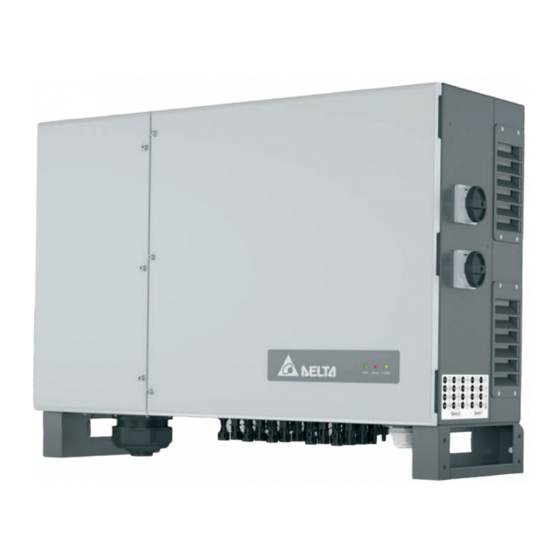
- Page 1 Installation and Operation Manual Solar inverters M125HV_110 / M125HV_111 (Delta part numbers RPI124M110000 / RPI124M111000) Europe Installation and Operation Manual M125HV EU V3 EN 2021-07-12...
- Page 2 ● M125HV_111 (Delta part number RPI124M111000) The Delta part number can be found on the type plate of the inverter. The product version is shown by the last letter of the serial number, which is also located on the type plate. The firm- ware versions can be read out with the DSS software.
-
Page 3: Table Of Contents
Table of Contents 1. About this manual ............6 Purpose of this manual. - Page 4 Commissioning steps with the Delta Service software........
- Page 5 Install type-1 AC surge protection device ......... . 90 9.3.1 Preparing type-1 AC surge protection devices for installation .
-
Page 6: About This Manual
WARNING Delta Electronics is not responsible for damage resulting from failure to follow the safety and operating instructions set out in Indicates a dangerous situation that can lead to death or this manual. -
Page 7: Writing And Labeling Conventions
1 About this manual Writing and labeling conventions Writing and labeling conventions Some sections in this manual are specially labeled. Labeling of work instructions Work instructions that must be performed in a specific sequence are numbered accordingly. Numbered work instructions must always be performed in the specified sequence. -
Page 8: Basic Safety Instructions
● of the connections can be restored acciden- All repair work on the inverter must be carried out by Delta tally. Electronics. Otherwise the warranty will be void. ●... -
Page 9: Intended Purpose
3 Intended purpose Intended purpose The inverter may be used only for the specified intended pur- pose. The intended purpose of the inverter is defined as follows: ● Use in stationary solar systems that are connected to the public grid. For conversion of the DC power that is generat- ed by the solar modules of the solar system into AC power which is fed into the local power grid. -
Page 10: Product Overview
4 Product overview Scope of delivery Product overview Scope of delivery Part Description Part Description Installation material for the inverter For mounting the inverter Inverter Mounting plate For fixing the feet when wall For fixing the feet when floor mounting mounting Mounting bracket for Mounting bracket for... - Page 11 4 Product overview Scope of delivery Part Description Part Description To unscrew the door screws and to secure the open doors from slam- Quick installation ming shut. guide and basic safety Allen wrench instructions Quick Installation Guide Solar power inverter M125HV European Union United Kingdom...
- Page 12 4 Product overview Scope of delivery All mounting material for the use of type-1 surge protection devices is supplied with the inverter. The type-1 surge protection devices themselves arenot included in the scope of delivery. Check the delivery for completeness and all com- ponents for damage before starting installation work.
-
Page 13: Overview Of Components And Connections
4 Product overview Overview of components and connections Overview of components and connections Fig. 4.1: Overview of components and connections Air outlets Status LEDs Mounting plate for wall mounting Communication connection Type plate Grounding connection DC isolating switch 1 DC connection panel, connections 13 to 20 DC isolating switch 2 DC connection panel, connections 1 to 12 Air inlets with fan modules... - Page 14 4 Product overview Overview of components and connections Fig. 4.2: Overview of components inside the inverter 13 Integrated AC surge protection devices type 2 17 DC string fuses minus (top) and plus (bottom) 14 Internal fan 2 18 Preliminary setup for DC surge protection devices type 1 15 Integrated type-2 DC surge protection devices;...
-
Page 15: Leds
4 Product overview LEDs LEDs Grid Alarm Explanation Countdown (inverter is starting up). The inverter is connected to the grid. Error. Power-off via external signal. Warning. Solar system failure. Grid Grid LED Green Solar system warning. Alarm Alarm LED Red/yellow No DC. -
Page 16: Ac-Side Components
4 Product overview AC-side components AC-side components 4.4.2 AC connection terminal 4.4.1 AC cable bushing Standard AC cable feed-through with 1 cable gland Fig. 4.5: AC connection terminal The AC terminal is suitable for networks with 3 phases and PE. The connection of a neutral conductor is not intended. -
Page 17: Type-2 Ac Surge Protection Devices
4 Product overview AC-side components 4.4.3 Type-2 AC surge protection devices 4.4.4 Preliminary setup for type-1 AC surge pro- tection devices Fig. 4.6: Cover of the type-2 AC surge protection devices Fig. 4.8: Connection components for AC surge protection The position of the type-2 AC surge protection devices is marked devices type 1 in the inverter with AC SPD. -
Page 18: Dc-Side Components
4 Product overview DC-side components 4.5.2 DC isolating switches DC-side components 4.5.1 DC Connections Fig. 4.10: DC isolating switch The inverter has two DC isolating switches, but only one MPP tracker. Fig. 4.9: DC connection panels The DC isolating switches are marked with "DC SWITCH" on the inverter. -
Page 19: Dc String Fuses
Instead of the pre-installed 20 A DC string fuses, identical 15 A DC string fuses from Littlefuse can be used. 15 A DC string fuses arenot available from Delta and must be ordered elsewhere. Related topics “6.3 Installing 15 A DC string fuses (optional)”, page 52... -
Page 20: Type 2 Dc Surge Protection Devices
4 Product overview DC-side components 4.5.4 Type 2 DC surge protection devices 4.5.5 Preliminary setup for type-1 DC surge pro- tection devices Fig. 4.16: Cover of the type-2 DC surge protection devices Fig. 4.18: View of the connection components for type-1 DC The position of the type-2 DC surge protection devices is marked surge protection devices with type-2 DC surge pro- in the inverter withDC SPD. -
Page 21: Communication Connection
4 Product overview Communication connection Communication connection Shielded and twisted pair cable Cable type (CAT5 or CAT6) Cable diameter 7.2 / 8.7 / 10.0 mm Wire cross section 0.25 ... 1.5 mm Table 4.8.: Specification of the communication cables Related topics “5.6 Grid and system protection”, page 44 “6.6 Connecting the communication card”, page 59 Fig. -
Page 22: Grounding Connections
4 Product overview Grounding connections Grounding connections 4.7.2 PE screw 4.7.1 Grounding screws Fig. 4.22: PE screw inside the inverter For an IT-type grounding system, the inverter housing must be connected to ground either via the PE screw of the AC connec- Fig. -
Page 23: Cooling System
4 Product overview Cooling system 4.8.2 Internal fans Cooling system The position of the two internal fans is marked in the inverter withInternal Fan 1 (behind the right door) and Internal Fan 2 4.8.1 Air inlets, air outlets and fan modules (behind the left door). - Page 24 4 Product overview Cooling system Internal fan 2 Fig. 4.28: Position of internal fan 2 Fig. 4.29: View of internal fan 2 with cover removed Related topics “10.6 Clean/replace internal fan 1”, page 116 “10.7 Clean/replace internal fan 2”, page 122 Installation and Operation Manual M125HV EU V3 EN 2021-07-12...
-
Page 25: Information On The Type Plate
4 Product overview Information on the type plate Information on the type plate Information on the type plate Description Risk of death due to electric shock Potentially fatal voltage is present inside the inverter during operation and this volt- age remains present for up to 135 seconds after disconnection from the power sup- 135 seconds ply. -
Page 26: Planning The Installation
5 Planning the installation Installation location Planning the installation This chapter describes only the planning of the installation work. The execution of the instal- lation work and the associated dangers are described in the "Installation" chapter. Installation location 5.1.1 Requirements for the Wall and Mounting System Fig. -
Page 27: Mounting Alignment
5 Planning the installation Installation location 5.1.2 Mounting Alignment 5.1.4 Lifting and Transporting the Inverter ► Mount the inverter vertically. ► Attach M12 eyebolts to the top side of the inverter. The screw eyebolts are not included in the scope of delivery. 5.1.3 Outdoor Installations ►... -
Page 28: Installation Clearances And Air Circulation
5 Planning the installation 5.1.5 Installation clearances and air circulation >50 cm >1 m >50 cm >94 cm >61 cm and air circulation Fig. 5.3: Installation Clearances and Air Circulation ► Ensure sufficient air circulation. Hot air must be able to ►... -
Page 29: Characteristic Curves
5 Planning the installation Characteristic curves Characteristic curves = 125 kW) = 600 V cos phi = 0,90 110% 100% 860 V 1050 V 1250 V Ambient temperature [°C] Characteristic curve "Active power control depending on the ambient temperature; cos φ = 0.90; AC voltage = 600 V Fig. - Page 30 5 Planning the installation Characteristic curves = 125 kW) = 600 V cos phi = 1,00 110% 100% 860 V 1050 V 1250 V Ambient temperature [°C] Characteristic curve "Active power control depending on the ambient temperature; cos φ = 1.0; AC voltage = 600 V Fig.
- Page 31 5 Planning the installation Characteristic curves = 125 kVA) = 600 V cos phi = 0,90 110% 100% 860 V 1050 V 1250 V Ambient temperature [°C] Characteristic curve "Apparent power control depending on the ambient temperature; cos φ = 0.90; AC voltage = 600 V Fig.
- Page 32 5 Planning the installation Characteristic curves = 125 kVA) = 600 V cos phi = 1,00 110% 100% 860 V 1050 V 1250 V 1350 V Ambient temperature [°C] Characteristic curve "Apparent power control depending on the ambient temperature; cos φ = 1.0; AC voltage = 600 V Fig.
- Page 33 5 Planning the installation Characteristic curves = 125 kW) = 600 V cos phi = 0,90 110% 100% 0 °C 25 °C 40 °C 50 °C 1050 1150 1250 1350 1450 1500 DC Input voltage [ Characteristic curve "Active power control depending on the DC input voltage; cos φ = 0.90; AC voltage = 600 V Fig.
- Page 34 5 Planning the installation Characteristic curves = 125 kW) = 600 V cos phi = 1,00 110% 100% 0 °C 25 °C 40 °C 50 °C 1050 1150 1250 1350 1450 1500 DC Input voltage [ Characteristic curve "Active power control depending on the DC input voltage; cos φ = 1.0; AC voltage = 600 V Fig.
- Page 35 5 Planning the installation Characteristic curves Efficiency [%] = 600 V 100% 860 V 1050 V 1250 V 1350 V AC Output power P/P [%]; P = 125 kW Efficiency characteristic curve; AC voltage = 600 V Fig. 5.10: Installation and Operation Manual M125HV EU V3 EN 2021-07-12...
-
Page 36: Dimensions
5 Planning the installation Dimensions Dimensions Front view with mounting brackets for wall mounting Top view with mounting brackets for floor mounting Dimensions in mm Fig. 5.11: Dimensions (in mm) Installation and Operation Manual M125HV EU V3 EN 2021-07-12... -
Page 37: Planning The Grid Connection (Ac)
This means that the inverter meets the require- ments of DIN VDE 0100-712. Possible error events were assessed by Delta in accordance with the current installation standards. The assessments showed that no hazards arise from operating the inverter in combination with an upstream, type A residual current circuit breaker (FI circuit breaker, RCD). -
Page 38: Grounding The Inverter
5 Planning the installation Planning the grid connection (AC) 5.4.6 Grounding the inverter WARNING High current ► Always observe the local regulations relating to grounding cable requirements. ► To increase the safety of the system, always use the grounding screw to ground the inverter housing even when this is not required by the local regulations. -
Page 39: Permissible Grid Voltages
5 Planning the installation Planning the grid connection (AC) 5.4.7 Permissible grid voltages Cable diameter of PE conductor ??? to ??? mm 3P3W Voltage Range Table 5.3.: Technical specification of the optional AC cable feed- L1-L2 600 V -36%/+15% through with four AC cable glands L2-L3 600 V -36%/+15%... - Page 40 5 Planning the installation Planning the grid connection (AC) 5.4.8.4 Cable lug selection NOTICE Select the cable lugs according to the following tables: Extreme temperature rise at the clamping Material of the AC terminal: tin coated point If the contact resistance between the aluminum Cables Cable lug conductor and cable lug is too high, the clamp-...
-
Page 41: Routing The Ac Cable
5 Planning the installation Planning the grid connection (AC) 5.4.9 Routing the AC cable When bending and twisting cables or conductors, always comply with the manufacturer’s instruc- tions so as to avoid breakage of the conductors or the insulation. When installing the inverter, always allow suffi- cient space below so that the AC cable can be easily inserted into the inverter. -
Page 42: Ac Cable Gland
5 Planning the installation Planning the grid connection (AC) 5.4.11 AC cable gland The inverter has 1 AC cable gland with 1 cable feed-through. Min./max. Cable diameter 23.9 ... 51.3 mm Notes on calculating the cable cross-section Consider the following factors when calculating the cable cross-section: ●... -
Page 43: Planning The Connection Of The Solar Modules (Dc)
5 Planning the installation Planning the grid connection (AC) ► Before connecting the solar modules, turn both DC isolating Planning the connection of the solar switches to the OFF position. modules (DC) Further information “6.7 Connect the mains (AC) and solar modules (DC)”, page 73 5.5.1 Safety instructions DANGER... -
Page 44: Dc Cable Requirements
5 Planning the installation Grid and system protection 5.5.4 DC cable requirements Grid and system protection The DC plugs for all DC connections are supplied with the 1. The German standard VDE-AR-N 4105 requires external inverter. mains and system protection with a coupling switch for PV systems larger than 30 kVA. -
Page 45: Device Communication And System Monitoring
5 Planning the installation Device communication and system monitoring 5.7.2 Specification of the communication cable Device communication and system monitoring Shielded and twisted pair cable Cable type (CAT5 or CAT6) Cable diameter 7.2 / 8.7 / 10.0 mm Related topics Wire cross section 0.25 ... -
Page 46: Connecting A Data Logger
The inverter has two multifunction relays allowing connection of NOTICE an acoustic or visual alarm unit to each. An event can be assigned to the dry contacts with Delta Service Unwanted currents. Software after commissioning. In some installation variants, unwanted currents can flow when multiple inverters are connected The Delta Service Software can be downloaded from www. -
Page 47: External Power-Off
Standard USB/RS485 adapter inverter For changing the inverter Delta Service Software settings To select a suitable USB/RS485 adapter, please contact Delta Customer Service. The Delta Service Software can be downloaded from www. solar-inverter.com. Cable requirements Bell wire. Both ends open. -
Page 48: Use Of Type-1 Ac Surge Protection Devices
5 Planning the installation Use of type-1 AC surge protection devices Use of type-1 AC surge protection de- Observe the restrictions regarding the dimensions vices of the type-1 AC surge protection devices! The dimensions specified inFig. 5.19, p. 48 must not be exceeded! For example, a Phoenix Contact type-1/2 surge Related topics... -
Page 49: Use Of Type-1 Dc Surge Protection Devices
5 Planning the installation Use of type-1 AC surge protection devices Use of type-1 DC surge protection de- Observe the restrictions regarding the dimensions vices of the type-1 DC surge protection devices! The dimensions specified inFig. 5.20, p. 49 must not be exceeded! For example, a Phoenix Contact type-1/2 search Related topics... -
Page 50: Installation
6 Installation Safety instructions Installation WARNING Electric shock ► Read chapter “5. Planning the installation”, If the doors of the inverter are open, the IP65 page 26 and this chapter in full before degree of protection is no longer guaranteed. ►... -
Page 51: Sequence Of Work Steps
6 Installation Sequence of work steps Sequence of work steps Step Notes Chapter Optional work on the inverter carried out before moving the inverter to the installation location. Installing type-1 AC surge protection device This step is only necessary if you want to “9.3 Install type-1 AC surge protection (optional) use type-1 AC surge protection devices... -
Page 52: Installing 15 A Dc String Fuses (Optional)
6 Installation Installing 15 A DC string fuses (optional) Installing 15 A DC string fuses (option- Content is not yet defined. Installation and Operation Manual M125HV EU V3 EN 2021-07-12... -
Page 53: Mounting The Inverter
6 Installation Mounting the inverter Mounting the inverter 6.4.1 Ground mounting (upright) 1. Screw the 4 mounting brackets for ground mounting to the feet of the inverter with 2 M10 screws (torque: 15 Nm), a spring washer and a washer each. The screws are sup- plied in the scope of delivery. -
Page 54: Wall Mounting
Deviations from this are only possible in exceptional cases approved by Delta Electronics. Always check with Delta Customer Service first if you want to deviate from the work instructions given in this section. 1. Screw the mounting bracket for wall mounting to the feet of the inverter with 2 M10 screws (torque: 15 Nm), a spring washer and a washer each. - Page 55 6 Installation Mounting the inverter 3. Mount the inverter on the mounting plate using a lifting device. 4. Check that the inverter is correctly mounted on the mount- ing plate. 5. Attach the mounting plate on the inverter feet to wall/the mounting system with 1 M10 screw each.
-
Page 56: Grounding The Inverter Housing
6 Installation Grounding the inverter housing Grounding the inverter housing WARNING High current ► Always observe the local regulations relating to grounding cable requirements. ► To increase the safety of the system, always ground the inverter housing even when this is not required by the local regulations. -
Page 57: Grounding Via The Pe Screw Of The Ac Connection
6 Installation Grounding the inverter housing 6.5.2 Grounding via the PE screw of the AC con- nection Cable lug selection Select the cable lugs according to the following tables: PE terminal material: nickel-plated Cables Cable lug ● Copper, tin coated Copper ●... - Page 58 6 Installation Grounding the inverter housing 2. Perform a continuity check of the grounding connection. Installation and Operation Manual M125HV EU V3 EN 2021-07-12...
-
Page 59: Connecting The Communication Card
6 Installation Connecting the communication card 6.6.2 Specification of the communication cable Connecting the communication card Shielded and twisted pair cable Cable type The connections for RS485, the dry contacts, the (CAT5 or CAT6) digital inputs and the external power-off (EPO) Cable diameter 7.2 / 8.7 / 10.0 mm are all on the communication card. -
Page 60: Initial Steps
6 Installation Connecting the communication card 6.6.3 Initial steps 1. Unscrew the cable gland of the communication connection and remove the cable gland and seal. 2. Unscrew and carefully pull out the cover. The communica- tions card is screwed onto the cover. Installation and Operation Manual M125HV EU V3 EN 2021-07-12... - Page 61 6 Installation Connecting the communication card 3. Remove the same number of rubber plugs from the seal corresponding to the number of cables to be connected. Do not remove the rubber plugs from the unused seal feed-throughs. 4. Pull the cable through the cable gland and seal. Installation and Operation Manual M125HV EU V3 EN 2021-07-12...
-
Page 62: Connecting A Data Logger Via Rs485
6 Installation Connecting the communication card DIP switch for the RS485 termination resistor 6.6.4 Connecting a data logger via RS485 6.6.4.1 Introduction NOTICE Unwanted currents. In some installation variants, unwanted currents can flow when multiple inverters are connected via RS485. ►... - Page 63 6 Installation Connecting the communication card Wiring diagram for multiple inverters ► If the data logger does not have an integrated RS485 termination resistor, switch the DIP switch for the RS485 termination resistor on the last inverter to (ON). ► Set a different inverter ID at each inverter during commis- sioning of the inverters.
- Page 64 6 Installation Connecting the communication card 6.6.4.2 Wiring for a single inverter 1. Connect the DATA+ wire to terminal 5 and the DATA– wire to terminal 6. 2. Set the DIP switch for the RS485 termination resistor (DIP 2) to the ON position. Installation and Operation Manual M125HV EU V3 EN 2021-07-12...
- Page 65 6 Installation Connecting the communication card 6.6.4.3 Wiring for multiple inverters Data logger 1. On the cable coming from the data logger: Connect the DATA+ wire to terminal 5 and the DATA– wire to terminal On the cable going to the second inverter: Connect the DATA+ wire to terminal 3 and the DATA–...
- Page 66 6 Installation Connecting the communication card Data logger 3. On the cable coming from the previous inverter: Con- nect the DATA+ wire to terminal 5 and the DATA– wire to terminal 6. On the cable going to the next inverter: Connect the DATA+ wire to terminal 3 and the DATA–...
- Page 67 6 Installation Connecting the communication card Data logger 5. Connect the DATA+ wire to terminal 5 and the DATA– wire to terminal 6. 6. Set the DIP switch for the RS485 termination resistor (DIP 2) to the ON position. Installation and Operation Manual M125HV EU V3 EN 2021-07-12...
-
Page 68: Connecting An External Alarm Unit
1. Connect two wires of the cable to one of the two dry contacts. 2. After commissioning with Delta Service Software, assign the alarm device an event at which it triggers. Installation and Operation Manual M125HV EU V3 EN 2021-07-12... - Page 69 1 ant 2 1. Connect the wires according to the desired connection diagram. 2. An event can be assigned to the dry contacts with Delta Service Software after commissioning. Installation and Operation Manual M125HV EU V3 EN 2021-07-12...
- Page 70 2 external alarm units, vari- ant 1 ant 2 1. Connect the wires according to the desired connection diagram. 2. An event can be assigned to the dry contacts with Delta Service Software after commissioning. Installation and Operation Manual M125HV EU V3 EN 2021-07-12...
-
Page 71: Connecting A Ripple Control Receiver
1. Connect the wires to the terminals V1 and K0. 2. After commissioning, the relay for the external power-off can be defined with Delta Service Software as a normally closed or normally open contact. Installation and Operation Manual M125HV EU V3 EN 2021-07-12... -
Page 72: Final Work
6 Installation Connecting the communication card 6.6.8 Final work 1. Insert the communication card and screw it in place. 2. Insert the seal and cable gland of the communication con- nection and fasten the cable gland. Installation and Operation Manual M125HV EU V3 EN 2021-07-12... -
Page 73: Connect The Mains (Ac) And Solar Modules (Dc)
6 Installation Connect the mains (AC) and solar modules (DC) Connect the mains (AC) and solar modules (DC) ∅ 33.0 ... 44,8 mm ∅ 44.8 ... 58.2 mm ∅ 58.2 ... 65,1 mm ∅ 65.1 ... 72,5 mm ∅ 72.5 ... 76.8 mm Fig. - Page 74 6 Installation Connect the mains (AC) and solar modules (DC) 3. Insert the AC cable with cover and AC cable gland. 4. Screw on the cover of the AC connection (torque: 0.8 Nm). 5. Fit and screw on the conductors of the AC cable (torque 25 Nm).
- Page 75 6 Installation Connect the mains (AC) and solar modules (DC) 6. Close both doors and screw them in with a torque Allen wrench (torque: 4.4 Nm). NOTE: Ensure doors and screws are straight! 7. Plug in the DC cables. 8. Turn both DC isolating switches to the ON position. →...
-
Page 76: Attaching Warning Labels To The Inverter
6 Installation Attaching warning labels to the inverter Attaching warning labels to the inverter All countries ► Attach all necessary warning labels to the inverter. Always follow the local regulations. Installation and Operation Manual M125HV EU V3 EN 2021-07-12... -
Page 77: Connecting A Pc Via Rs485
6 Installation Connecting a PC via RS485 Connecting a PC via RS485 Inverter USB/RS485 adapter DATA+ Terminal 3 or 5 DATA– Terminal 4 or 6 D– Installation and Operation Manual M125HV EU V3 EN 2021-07-12... -
Page 78: Commissioning
The PC is connected to the RS485 bus via a USB/ RS485 adaptor (see “6.9 Connecting a PC via RS485”, page 77). ● The Delta Service Software (DSS) is installed on the PC. Download link: https://solarsolutions.delta-emea.com/en/ Solar-Inverter-Support-171.htm Commissioning steps with the Delta... -
Page 79: Error Events And Troubleshooting
When the inverter is disconnected from all power sources, this Only Delta Customer Service is permitted to voltage remains in the inverter for up to 135 seconds. perform repair work and replace inverter com- You should therefore always carry out the fol- ponents. -
Page 80: Error
Non-linear load in the grid and in the vicinity of it further away. Grid Quality the inverter. If this error occurs repeatedly, contact Delta Customer Service. HW Connect Fail AC cable is not connected correctly. Check that the AC cable is connected correctly. -
Page 81: Warnings
8 Error events and troubleshooting Warnings Warnings Number Message Possible causes Correction suggestions Check the DC input voltage on the inverter dis- play. Solar Low DC input voltage is too low. There may be insufficient solar radiation. One or more fans are blocked. Clean or replace the fans. -
Page 82: Faults
Faults Number Message Possible causes Correction suggestions The grid waveform is abnormal. Contact Delta Customer Service. F01, F02, HW DC Injection Internal error. Contact Delta Customer Service. Temperature High The ambient temperature is > 60 °C. Check the system environment. - Page 83 8 Error events and troubleshooting Faults Number Message Possible causes Correction suggestions F36, F37, Overvoltage during operation. Contact Delta Customer Service. AC Current High F38, F39, Internal error. Contact Delta Customer Service. F40, F41 HW CT A Fail Internal error.
-
Page 84: Installing Accessories
9 Installing accessories Safety Instructions Installing accessories WARNING Heavy weight Safety Instructions The inverter is very heavy. ► The inverter must be lifted and carried by at least three people or using appropriate lifting DANGER gear example, a hoist or crane). Electric shock Potentially fatal voltages are present in the Before installing accessories, always start work... -
Page 85: Making Preparations For Work - Disconnecting The Inverter From The Mains (Ac) And Solar Modules (Dc)
9 Installing accessories Making preparations for work - disconnecting the inverter from the mains (AC) and solar modules (DC) Making preparations for work - discon- necting the inverter from the mains (AC) and solar modules (DC) The work instructions in this section apply to all maintenance work. - Page 86 9 Installing accessories Making preparations for work - disconnecting the inverter from the mains (AC) and solar modules (DC) 2. Turn both DC isolating switches to the OFF position. 3. Wait at least 135 seconds until the internal capacitors have discharged. 4.
- Page 87 9 Installing accessories Making preparations for work - disconnecting the inverter from the mains (AC) and solar modules (DC) 5. Secure the left-hand door with the Allen wrench. 6. Screw on the right-hand door with the other Allen wrench supplied. 7.
- Page 88 9 Installing accessories Making preparations for work - disconnecting the inverter from the mains (AC) and solar modules (DC) 8. Use a voltmeter to check that there is no more voltage at the AC connection. → If you detect voltage, open the external load isolating switch.
- Page 89 9 Installing accessories Making preparations for work - disconnecting the inverter from the mains (AC) and solar modules (DC) 11. Unscrew and pull out the wires of the AC cable. 12. Unscrew the cover of the AC cable gland and pull out the cable with cover and AC cable gland.
-
Page 90: Install Type-1 Ac Surge Protection Device
9 Installing accessories Install type-1 AC surge protection device Install type-1 AC surge protection de- vice DANGER Electric shock Potentially fatal voltages are present in the inverter during operation. When the inverter is disconnected from all power sources, this voltage remains in the inverter for up to 135 seconds. -
Page 91: Installing And Connecting Ac Surge Protection Devices
9 Installing accessories Install type-1 AC surge protection device 9.3.2 Installing and connecting AC surge protection devices 1. Unscrew and remove the cover of the type-2 AC surge protection devices. 2. Unscrew and remove the power cables of the type-2 AC surge protection devices. - Page 92 9 Installing accessories Install type-1 AC surge protection device 3. Retighten the nuts with the washers. 4. Pull the plug with the PCB cable out of the socket for the type-2 AC surge protection devices and insert it in the socket for the type-1 AC surge protection devices.
- Page 93 9 Installing accessories Install type-1 AC surge protection device 5. Unscrew and remove the cover of the type-1 AC surge protection devices. Installation and Operation Manual M125HV EU V3 EN 2021-07-12...
- Page 94 9 Installing accessories Install type-1 AC surge protection device 6. Connect the type-1 wired AC surge protection devices to the DIN rail. 7. Install the cover of the type-1 AC surge protection devices. 8. Secure the DIN rail to the type-1 AC surge protection devices and the cover.
- Page 95 9 Installing accessories Install type-1 AC surge protection device 9. Secure the PE cable to the DIN rail. 10. Insert the plug with the signal cable into the socket for the type-1 AC surge protection devices. Installation and Operation Manual M125HV EU V3 EN 2021-07-12...
- Page 96 9 Installing accessories Install type-1 AC surge protection device 11. Insert the plug with the power cable in the socket for the type-1 AC surge protection devices. The cabling should now look like this. 12. Insert the cover of the type-2 AC surge protection devices and screw it into place.
- Page 97 9 Installing accessories Install type-1 AC surge protection device 13. To complete the installation work, follow the instructions in the following section: “9.5 Finishing the work - connect- ing the inverter to the grid (AC) and solar modules (DC)”, page 99. Installation and Operation Manual M125HV EU V3 EN 2021-07-12...
-
Page 98: Install Type-1 Dc Surge Protection Devices
9 Installing accessories Install type-1 DC surge protection devices Install type-1 DC surge protection de- vices DANGER Electric shock Potentially fatal voltages are present in the inverter during operation. When the inverter is disconnected from all power sources, this voltage remains in the inverter for up to 135 seconds. -
Page 99: Finishing The Work - Connecting The Inverter To The Grid (Ac) And Solar Modules (Dc)
9 Installing accessories Finishing the work - connecting the inverter to the grid (AC) and solar modules (DC) Finishing the work - connecting the inverter to the grid (AC) and solar modules (DC) There is normally an isolating switch (for example in an equipment terminal box) between the inverter and the grid and between the solar mod- ules. - Page 100 9 Installing accessories Finishing the work - connecting the inverter to the grid (AC) and solar modules (DC) 17. Close both doors and screw them in with a torque Allen wrench (torque: 4.4 Nm). NOTE: Ensure doors and screws are straight! 18.
- Page 101 9 Installing accessories Finishing the work - connecting the inverter to the grid (AC) and solar modules (DC) 19. To re-establish the connection between inverter and mains or inverter and solar modules, close the load isolating switch. 20. Turn both DC isolating switches to the ON position. →...
-
Page 102: Maintenance
10 Maintenance Safety Instructions Maintenance WARNING Heavy weight 10.1 Safety Instructions The inverter is very heavy. ► The inverter must be lifted and carried by at least three people or using appropriate lifting DANGER gear example, a hoist or crane). Electric shock Potentially fatal voltages are present in the Always start all maintenance and replacement... -
Page 103: Periodic Maintenance
10 Maintenance Periodic maintenance 10.2 Periodic maintenance Perform the following checks every 6 months. ● Visual inspection of all cables and connectors for external damage. ● Check the string fuses. Measure the current using a current transformer. ● Checking the fans. Perform the following checks every three months ●... -
Page 104: Making Preparations For Maintenance Work - Disconnecting The Inverter From The Grid (Ac) And Solar Modules (Dc)
10 Maintenance Making preparations for maintenance work - disconnecting the inverter from the grid (AC) and solar modules (DC) 10.4 Making preparations for maintenance work - disconnecting the inverter from the grid (AC) and solar modules (DC) The work instructions in this section apply to all maintenance work. - Page 105 10 Maintenance Making preparations for maintenance work - disconnecting the inverter from the grid (AC) and solar modules (DC) 2. Turn both DC isolating switches to the OFF position. 3. Wait at least 135 seconds until the internal capacitors have discharged. 4.
- Page 106 10 Maintenance Making preparations for maintenance work - disconnecting the inverter from the grid (AC) and solar modules (DC) 5. Secure the left-hand door with the Allen wrench. 6. Screw on the right-hand door with the other Allen wrench supplied. 7.
- Page 107 10 Maintenance Making preparations for maintenance work - disconnecting the inverter from the grid (AC) and solar modules (DC) 8. Use a voltmeter to check that there is no more voltage at the AC connection. → If you detect voltage, open the external load isolating switch.
- Page 108 10 Maintenance Making preparations for maintenance work - disconnecting the inverter from the grid (AC) and solar modules (DC) 11. Unscrew and pull out the wires of the AC cable. 12. Unscrew the cover of the AC cable gland and pull out the cable with cover and AC cable gland.
-
Page 109: Clean/Replace Air Inlets, Air Outlets And Fan Modules
10 Maintenance Clean/replace air inlets, air outlets and fan modules 10.5 Clean/replace air inlets, air outlets and fan modules DANGER Electric shock Potentially fatal voltages are present in the inverter during operation. When the inverter is disconnected from all power sources, this voltage remains in the inverter for up to 135 seconds. - Page 110 10 Maintenance Clean/replace air inlets, air outlets and fan modules Clean air inlets and clean/replace fan modules The procedure is the same for both fan modules. The fan modules are replaced as a block ∫ 1. Unscrew and remove the air filter. 2.
- Page 111 10 Maintenance Clean/replace air inlets, air outlets and fan modules 3. Pull out the plugs of the two power supply cables. 4. Clean the air filter with a compressed air cleaner or a firm brush. Installation and Operation Manual M125HV EU V3 EN 2021-07-12...
- Page 112 10 Maintenance Clean/replace air inlets, air outlets and fan modules 5. Clean the fan module with a compressed air cleaner or a firm brush. 6. Insert the connectors of the 2 power supply cables until they snap into place. It does not matter which power cable you use for which fan.
- Page 113 10 Maintenance Clean/replace air inlets, air outlets and fan modules 8. Install the air filter with the fins facing downward and screw it in. Installation and Operation Manual M125HV EU V3 EN 2021-07-12...
- Page 114 10 Maintenance Clean/replace air inlets, air outlets and fan modules Cleaning the air outlets This procedure is the same for both air outlets. ∫ 9. Unscrew and remove the air filter. 10. Clean the air filter with a compressed air cleaner or a firm brush.
- Page 115 10 Maintenance Clean/replace air inlets, air outlets and fan modules 11. Insert and screw on the air filter. The fins must be facing downward. Completing work on the air filters and fan modules 12. To complete the maintenance work, follow the instructions in the following section: “10.10 Completing the mainte- nance work —...
-
Page 116: Clean/Replace Internal Fan 1
10 Maintenance Clean/replace internal fan 1 10.6 Clean/replace internal fan 1 DANGER Electric shock Potentially fatal voltages are present in the inverter during operation. When the inverter is disconnected from all power sources, this voltage remains in the inverter for up to 135 seconds. - Page 117 10 Maintenance Clean/replace internal fan 1 3. Disconnect the power supply cable of the fan. 4. Unscrew the metal housing with the screwed-in fan and carefully pull it out. Installation and Operation Manual M125HV EU V3 EN 2021-07-12...
- Page 118 10 Maintenance Clean/replace internal fan 1 This work step must only be carried out if the fan is to be replaced. The work step is not necessary for cleaning the fan. ∫ 5. Unscrew the fan from the metal housing and pull it out. 6.
- Page 119 10 Maintenance Clean/replace internal fan 1 This work step must only be carried out if the fan is to be replaced. The work step is not necessary for cleaning the fan. ∫ 7. Insert and screw the fan into the metal housing. 8.
- Page 120 10 Maintenance Clean/replace internal fan 1 9. Plug in the power supply cable of the fan. 10. Install and screw in the air baffle. 11. Insert the cover for the DC surge protection devices. Installation and Operation Manual M125HV EU V3 EN 2021-07-12...
- Page 121 10 Maintenance Clean/replace internal fan 1 12. To complete the maintenance work, follow the instructions in the following section: “10.10 Completing the mainte- nance work — connecting the inverter to the mains (AC) and solar modules (DC)”, page 136 Installation and Operation Manual M125HV EU V3 EN 2021-07-12...
-
Page 122: Clean/Replace Internal Fan 2
10 Maintenance Clean/replace internal fan 2 10.7 Clean/replace internal fan 2 DANGER Electric shock Potentially fatal voltages are present in the inverter during operation. When the inverter is disconnected from all power sources, this voltage remains in the inverter for up to 135 seconds. - Page 123 10 Maintenance Clean/replace internal fan 2 NOTICE Damage to the power supply cable. The power supply cable of the fan is relatively short. To avoid damage, carefully pull out the metal housing and only to the extent that the plug of the power supply is accessible. 2.
- Page 124 10 Maintenance Clean/replace internal fan 2 This work step must only be carried out if the fan is to be replaced. The work step is not necessary for cleaning the fan. ∫ 4. Unscrew the fan from the metal housing and pull it out. 5.
- Page 125 10 Maintenance Clean/replace internal fan 2 This work step must only be carried out if the fan is to be replaced. The work step is not necessary for cleaning the fan. ∫ 6. Insert and screw the fan into the metal housing. 7.
- Page 126 10 Maintenance Clean/replace internal fan 2 9. Screw in the metal housing with the screwed-in fan. 10. Insert and screw in the cover for the AC surge protection devices (torque: 0.8 Nm). Installation and Operation Manual M125HV EU V3 EN 2021-07-12...
- Page 127 10 Maintenance Clean/replace internal fan 2 11. To complete the maintenance work, follow the instructions in the following section: “10.10 Completing the mainte- nance work — connecting the inverter to the mains (AC) and solar modules (DC)”, page 136 Installation and Operation Manual M125HV EU V3 EN 2021-07-12...
-
Page 128: Replacing Type 2 Ac Surge Protection Devices
10 Maintenance Replacing type 2 AC surge protection devices 10.8 Replacing type 2 AC surge protection devices DANGER Electric shock Potentially fatal voltages are present in the inverter during operation. When the inverter is disconnected from all power sources, this voltage remains in the inverter for up to 135 seconds. - Page 129 10 Maintenance Replacing type 2 AC surge protection devices 3. Pull out the signal cable plug. 4. Unscrew and remove the card with the AC surge protec- tion devices. Installation and Operation Manual M125HV EU V3 EN 2021-07-12...
- Page 130 10 Maintenance Replacing type 2 AC surge protection devices 5. Insert and screw in the card with the new AC surge pro- tection devices. 6. Plug in the signal cable plug. 7. Screw in the power supply cable. Installation and Operation Manual M125HV EU V3 EN 2021-07-12...
- Page 131 10 Maintenance Replacing type 2 AC surge protection devices 8. Insert and screw in the cover of the AC surge protection devices. 9. To complete the maintenance work, follow the instructions in the following section: “10.10 Completing the mainte- nance work — connecting the inverter to the mains (AC) and solar modules (DC)”, page 136 Installation and Operation Manual M125HV EU V3 EN 2021-07-12...
-
Page 132: Replace Type 2 Dc Surge Protection Devices
(AC) and solar modules (DC)”, page 104 before you start work on the inverter! The surge protection devices are replaced as a block. You can obtain spare parts from Delta Customer Service. You can find the contact infor- ∫ mation on the back of this document. - Page 133 10 Maintenance Replace type 2 DC surge protection devices 3. Unscrew the signal cable plug and pull it out. 4. Unscrew and remove the card with the DC surge protec- tion devices. Installation and Operation Manual M125HV EU V3 EN 2021-07-12...
- Page 134 10 Maintenance Replace type 2 DC surge protection devices 5. Insert and screw in the card with the new DC surge pro- tection devices. 6. Insert the signal cable plug and screw it in. Installation and Operation Manual M125HV EU V3 EN 2021-07-12...
- Page 135 10 Maintenance Replace type 2 DC surge protection devices 7. Screw in the power supply cable. 8. Insert the cover for the DC surge protection devices. 9. To complete the maintenance work, follow the instructions in the following section: “10.10 Completing the mainte- nance work —...
-
Page 136: Completing The Maintenance Work - Connecting The Inverter To The Mains (Ac) And Solar Modules (Dc)
10 Maintenance Completing the maintenance work — connecting the inverter to the mains (AC) and solar modules (DC) 10.10 Completing the maintenance work — connecting the inverter to the mains (AC) and solar modules (DC) There is normally an isolating switch (for example in an equipment terminal box) between the inverter and the grid and between the solar mod- ules. - Page 137 10 Maintenance Completing the maintenance work — connecting the inverter to the mains (AC) and solar modules (DC) 13. Close both doors and screw them in with a torque Allen wrench (torque: 4.4 Nm). NOTE: Ensure doors and screws are straight! 14.
- Page 138 10 Maintenance Completing the maintenance work — connecting the inverter to the mains (AC) and solar modules (DC) 15. To re-establish the connection between inverter and mains or inverter and solar modules, close the load isolating switch. 16. Turn both DC isolating switches to the ON position. →...
-
Page 139: Replacing The Inverter
Delta Electronics. lowing steps before working on the inverter: 1. Turn both DC isolating switches to the OFF Delta Electronics will provide you with a fully position. featured replacement device. You will not need 2. Disconnect the inverter from all AC and DC... - Page 140 11 Replacing the inverter 1. Unpack the replacement device and place it on a stable storage area so that all components are easily accessible. 2. To shut off the old inverter's AC voltage, open the load isolating switch between the inverter and the mains con- nection point.
- Page 141 11 Replacing the inverter 5. Screw on the left-hand door using one of the Allen wrenches supplied. 6. Secure the left-hand door with the Allen wrench. 7. Screw on the right-hand door with the other Allen wrench supplied. Installation and Operation Manual M125HV EU V3 EN 2021-07-12...
- Page 142 11 Replacing the inverter 8. Secure the right-hand door with the Allen wrench. 9. Use a voltmeter to check that there is no more voltage at the AC connection. → If you detect voltage, open the external load isolating switch. →...
- Page 143 11 Replacing the inverter 11. Use the mounting tool to release the DC cables and then pull them out. 12. Remove the cover caps for the DC connections from the replacement device and connect them to the DC connec- tions of the old inverter. 13.
- Page 144 11 Replacing the inverter 14. Unscrew the cover of the AC cable feed-through and pull out the cable together with the cover and AC cable gland. 15. Unscrew the cover of the AC cable gland including the AC cable gland from the replacement device and screw it onto the old inverter.
- Page 145 11 Replacing the inverter 16. Unscrew the cover of the communication connection and carefully pull out the cover including the cable gland and cable. The communication card is attached to the cover. 17. On the replacement device, unscrew the cover of the com- munication connection and pull out the cable gland and communication card together.
- Page 146 11 Replacing the inverter 19. To lift and move the inverter, screw in 2 M12 eyebolts on the top of the inverter. 20. Secure the inverter with a block and tackle or with crane so that the weight will be suspended from the block and tackle after the mounting screws are loosened.
- Page 147 11 Replacing the inverter 21. Unscrew the grounding cable from the inverter. 22. Unscrew the mounting brackets at the feet of the inverter. Installation and Operation Manual M125HV EU V3 EN 2021-07-12...
- Page 148 24. Place all components of the replacement device that will not be needed back into the box. 25. Package and ship the old inverter in accordance with the notes received from Delta Customer Service. 26. Install and commission the new inverter in accordance with the installation instructions supplied.
-
Page 149: Technical Data
12 Technical Data Technical Data Input (DC) M125HV Maximum recommended PV power 250 kW Maximum input power 128 kW Rated power 125 kW Max. input voltage 1600 V Operating input voltage range 860 to 1500 V Rated voltage 1050 V Switch-on voltage 1050 V Switch-on power... - Page 150 140 kVA Maximum active power 125 kW Rated apparent power 125 kVA Rated voltage 600 V -36% / +15%, 3 phases + PE, delta connection (△) Rated current 120 A Maximum current 135 A Maximum current in case of fault...
- Page 151 Fluctuations and fibrillations EN 61000-3-3 You will find the current list at Grid connection guidelines solarsolution.delta-emea.com For cos phi = 1 (VA = W) AC rated voltage and frequency range will be programmed according to the individual country requirements. 1 m distance, 25°C ambient temperature...
- Page 152 +421 42 4661 333 Other European countries support.europe@solar-inverter.com +49 7641 455 549 © Copyright – Delta Electronics (Netherlands) B.V. – All rights reserved. All information and specifications can be modified without prior notice. Installation and Operation Manual M125HV EU V3 EN 2021-07-12...
Need help?
Do you have a question about the M125HV 110 and is the answer not in the manual?
Questions and answers