Table of Contents
Advertisement
Quick Links
Advertisement
Table of Contents

Related Manuals for Delta RPI H3 110


Summary of Contents for Delta RPI H3 110
-
Page 1: Quick Installation Guide
Quick Installation Guide RPI H3_110 Europe... -
Page 2: Table Of Contents
This manual applies for solar inverters models: © Copyright – Delta Energy Systems (Germany) GmbH – All ● rights reserved. RPI H3_110 with irmware version: DSP: 2.02 / RED: 2.01 / COMM: 2.00 This quick installation guide is included with our solar inverter and is intended for use by the installer. -
Page 3: General Safety Instructions
(see IEC 62109- inverter during operation. This potentially fatal 5.3.3). Delta Energy Systems is not responsible for damage incurred by failure to observe the installation and commis- voltage is still present for 15 seconds after all sioning instructions in this manual. -
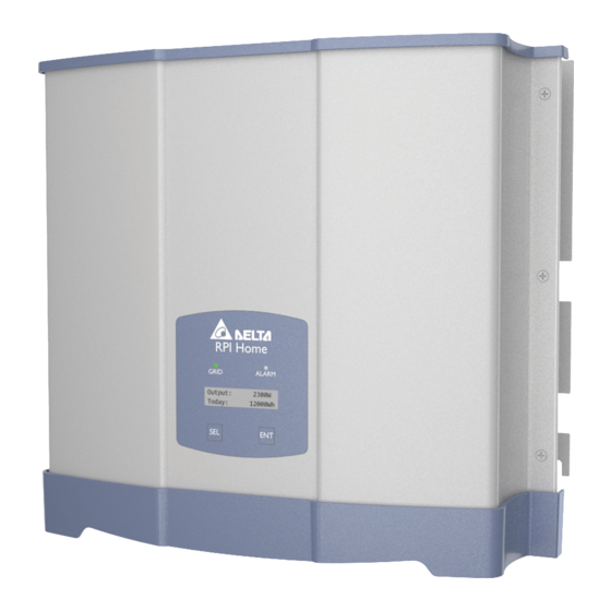
Page 4: Components Of The Inverter
Components of the inverter Display, buttons, LEDs Type label Electrical connectors DC Inputs RS485 Digital inputs and dry contacts DC switch AC Connector Designation Label Usage LEDs Green; lights up when the solar inverter feeds into the Grid grid Alarm Red;... -
Page 5: Information On The Type Label
Information on the type label Risk of death by electrocution Potentially fatal voltage is present when the solar inverter is in operation that remains for 15 seconds after being disconnected from power. 15 seconds Never open the solar inverter. The solar inverter contains no components that must be maintained or repaired by the operator or installer. -
Page 6: Planning The Installation
Planning the installation Where to mount the inverter ► Always use the mounting plate supplied with the inverter. ► Check that the wall is capable of bearing the heavy weight of the inverter. ► Use dowels and screws that are suitable for the wall material and the heavy weight. -
Page 7: Mounting The Inverter
Mounting the inverter ► Fasten the mounting plate with 6 M5 screws to the wall. ► Hang the inverter onto the mounting plate. ► Check that the rail of the inverter hangs correctly in the mounting plate and screw the inverter to the mounting plate. ►... -
Page 8: Connecting To The Grid (Ac)
DIN VDE 0100-712. When examining these possible fault situations in terms of the currently valid installation standards, Delta has come to the conclusion that there is no danger when operating the inverter in combination with a type A upstream residual-current device (RCD). - Page 9 Turn the DC disconnection switch to position OFF. ► Remove the cable housing with a 3.5 mm lat end screw- driver. Remove the cable sheath as shown and remove 12 mm of ► Slide cable nut and cable housing onto the AC cable in the insulation from each wire end.
- Page 10 Connecting to the grid (continued) ► Insert the AC plug into the AC connector on the inverter until you can hear a “click” sound. CLICK 0.8 ... 1 Nm ► Slide the cable housing into the socket insert until you can ►...
- Page 11 AC cable requirements Markings on the inverter Use properly sized wires (see table) In some countries, the following labels have to be applied on the front of each micro inverter. Please check applicable national and Wieland RST25i3S S1AZR2V local standards and regulations. AC plug BG03 (96.
-
Page 12: Connecting To The Solar Modules (Dc)
Connecting to the solar modules (DC) ► Turn the DC disconnection switch to position OFF, before you DANGER connect the DC cables. High electrocution Potentially fatal voltage may be applied to the DC connections of the solar inverter. When light is falling on solar modules, they immediately start producing energy. - Page 13 DC cable speciication DC connectors on the inverter Plugs for DC cable MultiContact 32.0010P0001-UR 1,5 / 2,5 5,5-9 32.0012P0001-UR DC– 3–6 32.0014P0001-UR 4 / 6 5,5-9 32.0016P0001-UR 32.0011P0001-UR 1,5 / 2,5 5,5-9 32.0013P0001-UR 32.0015P0001-UR 4 / 6 5,5-9 32.0017P0001-UR France: Safety caps are needed for each DC input that is connected to a string of solar modules.
-
Page 14: Connecting To A Datalogger Via Rs485
RS485. If you want to use SOLIVIA Monitor, the Internet based monitor- ing from Delta, you will also need a SOLIVIA M1 G2 Gateway. Default baud rate is 19200 which can be changed on the inverter (see chapter “Setting the baud rate”, p. - Page 15 Connecting a single inverter to a datalogger Connecting to a Delta SOLIVIA Gateway M1 G2 On the inverter you connect single wires, on the gateway you Termination resistor = ON have to use a RJ45 plug. Connect inverter and gateway according to the following table:...
-
Page 16: Connecting Digital Inputs And Dry Contacts (Optional)
Connecting a PC via RS485 If you want to use a PC with the Delta Service Software to set up the inverter, you need a USB/RS485 adapter to connect the PC to the RS485 terminal block of the inverter. - Page 17 Tips for wiring ► Carefully put in the terminal block of the digital inputs and ► Unscrew and carefully pull out the terminal block of the dry tighten the screws. contacts. ► Carefully put in the terminal block of the dry contacts and ►...
-
Page 18: Commissioning - Basic Settings
Commissioning - basic settings To execute commissioning, the inverter needs to be pow- ered either by AC (the grid) or DC (the solar modules) U K G 8 3 - 2 Use the button to select your country or grid. N e x t / E n t e r To conirm your selection, press the button To inish the country selection, press the button... -
Page 19: Baud Rate
Commissioning - Further settings (continued) Setting the baud rate C o u n t r y In the main menu, use the button to select Country. U K G 8 3 - 2 Press the buttons at the same time and hold them for at least 10 sec- onds. -
Page 20: Date And Time
Commissioning - Further settings (continued) Setting date and time C o u n t r y In the main menu, use the button to select Country. U K G 8 3 - 2 Press the buttons at the same time and hold them for at least 10 sec- onds. -
Page 21: Language
Setting the language C o u n t r y In the main menu, use the button to select Country. U K G 8 3 - 2 Press the buttons at the same time and hold them for at least 10 sec- onds. -
Page 22: Technical Data
Technical data Input (DC) RPI H3 Maximum recommended PV power 3780 W Maximum input power 3200 W Nominal power 3150 W Voltage range 125 ... 600 V Maximum input voltage 600 V MPP operating voltage range 125 ... 550 V MPP operating voltage range with full power 320 ... - Page 23 Wieland RST25i3S B1G M01 DC Connector type Multi-Contact MC4 Communication interfaces 2 x RS485, 1 x Dry contacts, 4 x Digital inputs General Speciication RPI H3 Delta model name RPI H3_110 Delta part number RPI302N63E0000 Maximum eficiency 97.0% EU eficiency 96.2%...
-
Page 24: Service Europe
+49 7641 455 549 5013227802 02 © Copyright – Delta Energy Systems (Germany) GmbH – All rights reserved. All information and speciications can be modiied without prior notice Quick installation guide for RPI H3 inverters EU EN 5013227802 02 2016-01-05.
Need help?
Do you have a question about the RPI H3 110 and is the answer not in the manual?
Questions and answers