Table of Contents
Advertisement
Quick Links
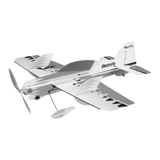
Wingspan: 34 in [865mm]
Wing Area: 291 sq in [18.8 dm
Weight: 8 – 9.5 oz [225 – 270g]
Wing Loading: 4 – 5 oz/sq ft [12 – 14 g/dm
Length: 34 in [865mm]
Radio: 4-channel w/3 micro servos and 10-Amp ESC
Power System: Included ElectriFly
or optional direct-drive RimFire
Great Planes
®
Model Manufacturing Co. guarantees this kit to be free from defects in both material and workmanship at the date of
purchase. This warranty does not cover any component parts damaged by use or modification. In no case shall Great Planes' liability
exceed the original cost of the purchased kit. Further, Great Planes reserves the right to change or modify this warranty without notice.
In that Great Planes has no control over the final assembly or material used for final assembly, no liability shall be assumed nor
accepted for any damage resulting from the use by the user of the final user-assembled product. By the act of using the user-assembled
product, the user accepts all resulting liability.
If the buyer is not prepared to accept the liability associated with the use of this product, the buyer is advised to return this
kit immediately in new and unused condition to the place of purchase.
To make a warranty claim send the defective part or item to Hobby Services at the address below:
Include a letter stating your name, return shipping address, as much contact information as possible (daytime telephone number, fax
number, e-mail address), a detailed description of the problem and a photocopy of the purchase receipt. Upon receipt of the package
the problem will be evaluated as quickly as possible.
READ THROUGH THIS MANUAL BEFORE STARTING
CONSTRUCTION. IT CONTAINS IMPORTANT WARNINGS
AND INSTRUCTIONS CONCERNING THE ASSEMBLY
AND USE OF THIS MODEL.
© Copyright 2005
INSTRUCTION MANUAL
2
]
2
]
™
ferrite motor with gearbox,
™
Brushless motor
3002 N. Apollo Dr., Suite 1
Champaign, IL 61822 USA
WARRANTY
Hobby Services
™
Champaign, Illinois
(217) 398-8970, Ext 5
airsupport@greatplanes.com
GPMZ0174 for GPMA1115 V1.1
By Great Planes
Advertisement
Table of Contents

Related Manuals for GREAT PLANES turmoil arf


Summary of Contents for GREAT PLANES turmoil arf
-
Page 1: Instruction Manual
Further, Great Planes reserves the right to change or modify this warranty without notice. In that Great Planes has no control over the final assembly or material used for final assembly, no liability shall be assumed nor accepted for any damage resulting from the use by the user of the final user-assembled product. -
Page 2: Table Of Contents
DECISIONS YOU MUST MAKE ........3 For the latest technical updates or manual corrections to the Transmitter ..............3 FlatOut Turmoil ARF visit the Great Planes web site at Servos................3 www.electrifly.com. Open the “Airplanes” link, then select Receiver...............3 the FlatOut Turmoil ARF. -
Page 3: Ama
3. Use an R/C radio system and components that are in first- In the hands of a capable pilot the FlatOut Turmoil ARF is an class condition. The FlatOut Turmoil ARF requires impressive 3D performer. But for the FlatOut Turmoil ARF to specialized radio gear. -
Page 4: Battery
(Channels 11-35) (Channels 36-60) R124F Receiver FUTL0438 FUTL0439 Rest assured, the FlatOut Turmoil ARF is capable of 3D flight Crystal FUTL62** FUTL63** with the included ElectriFly “stick-mount” motor and gearbox combination. But for pilots who always insist on upgrading and ** Replace the “**”... -
Page 5: Kit Inspection
If any parts are missing or are not of acceptable quality, or if you need assistance with assembly, contact Product Support. When reporting defective or missing parts, use the part names exactly as they are written in the Kit Contents list. Great Planes Product Support: 3002 N. Apollo Drive, Suite 1 Champaign, IL 61822 Telephone: (217) 398-8970, ext. -
Page 6: Ordering Replacement Parts
ORDERING REPLACEMENT PARTS Replacement parts for the Great Planes FlatOut Turmoil ARF are available using the order numbers in the Replacement Parts List that follows. The fastest, most economical service can be provided by your hobby dealer or mail-order company. -
Page 7: Build The Airplane
B. Coat both sides of one hinge (C2) with foam-safe CA BUILD THE AIRPLANE where it contacts the sides of the hinge slot. Rotate the hinge down into the slot. Be certain the top and bottom of the hinge remain flush with the top and bottom of the Assemble the Horizontal Stabilizer control surface you are hinging. - Page 8 THE CONTROL SURFACES CLEVISES EASIER Note: You may want to protect your work surface from excess glue. We recommend Great Planes Plan Protector (GPMR6167) for this purpose. A. Cut several 1-1/2" [38mm] pieces of removable cellophane tape. Fold the last 1/4" [6mm] over to make a tab for easy removal.
-
Page 9: Assemble The Wing
Assemble the Wing ❏ 1. Cut the wing and ailerons from the foam sheet. ❏ 4. Slide four hinge retainer rings (C3) onto the wing trailing edge tube. Position the rings so that they align with the inner slots in the TE of the wing. Secure each retainer with a drop of glue on the outside of the gap. - Page 10 ❏ 2. Glue the 5.5 x 146mm [7/32" x 5-3/4"] fuselage tube ❏ doubler over the 3 x 726mm [1/8" x 28-1/2"] fuselage tube. 6. Glue the left and right horizontal fuselage halves to the One end should be flush. From now on, this assembly will fuselage tube.
- Page 11 ❏ 10. Using the 3 x 160mm [1/8" x 6-1/4"] rudder post tube as a guide, glue four clip hinges (C2) and a clip hinge control ❏ horn (C1) to the rudder. The control horn should protrude from 14. Glue the 3 x 150mm [1/8" x 6"] strut brace tube into the right side of the rudder.
- Page 12 ❏ 17. Installing them from the left side, glue two more supports into the slots in the fuselage. Note that these first two supports should be positioned aft in the slots, and that the holes in the supports should be angled downward and ❏...
-
Page 13: Finish The Landing Gear
Finish the Landing Gear ❏ 1. Install a 2 x 17mm [5/64" x 21/32"] axle and axle support (D1) onto each landing gear leg. Make sure that the axles are perpendicular to the centerline. ❏ 2. Slide the wheels onto the axles, and secure them with a wheel collar (D6). -
Page 14: Radio Setup
❏ 5. Slide the tailwheel bracket over the rudder and rudder ❏ post. Glue the bracket to the rudder only . Do not glue the 5. With the output shaft forward, glue the aileron servo bracket to the rudder post. into the cutout under the wing. - Page 15 ❏ 12. Using the pushrod as a guide, drill two evenly-spaced ❏ 9. Using an Easy-Touch bar sander with 220-grit 2.4mm [3/32"] holes through the fuselage for the pushrod sandpaper, sharpen the ends of all the 1mm [3/64"] carbon guides. Glue the base of each pushrod guide into the holes. pushrods.
-
Page 16: Mount The Motor & Gearbox
Mount the Motor & Gearbox If mounting the included stick-mounted motor and gearbox or an after-market geared brushless system, follow the instructions in this section. If mounting a firewall-mounted motor system, proceed to “Firewall-Mounted Motor System” on page 17. ❏ ❏... -
Page 17: Firewall-Mounted Motor System
❏ 3. If installing an ElectriFly RimFire motor, glue the ❏ 9. Install the “hook” side of the included hook-and-loop included 3mm [1/8"] plywood firewall to the nose so that the material to the left side of the fuselage where shown. This is two pilot holes are centered on the horizontal fuselage, and where you will mount the battery. -
Page 18: Set The Control Throws
❏ 3. Lower the throttle stick all the way and turn on the transmitter. Connect your battery to the ESC. If the ESC has a BEC switch, turn it on. ❏ 4. Check all the control surfaces to see if they are centered. -
Page 19: Balance The Model Laterally
Balance the Model Laterally ❏ 1. With the wing level, lift the model by the engine propeller shaft and the bottom of the fuse under the TE of the fin. Do this several times. ❏ 2. If one wing always drops when you lift the model, it means that side is heavy. -
Page 20: Motor Safety Precautions
work the controls, tell you what the control surfaces are doing. RADIO CONTROL Repeat this test with the motor running at various speeds 1) I will have completed a successful radio equipment ground with an assistant holding the model, using hand signals to check before the first flight of a new or repaired model. -
Page 21: Flying
For more information, log on at www.electrifly.com – and be amazed. 1-year When flying a 3D aerobat like the FlatOut Turmoil ARF, there warranty. GPMM3150 are several things you should always keep in mind. First is throttle management–this airplane has enough power to... - Page 22 BUILDING NOTES Kit Purchased Date: _______________________ Date Construction Finished: _________________ Where Purchased:_________________________ Finished Weight: __________________________ Date Construction Started: __________________ Date of First Flight: ________________________ FLIGHT LOG...
-
Page 23: Angle Templates
ANGLE TEMPLATES...
Need help?
Do you have a question about the turmoil arf and is the answer not in the manual?
Questions and answers