Table of Contents
Advertisement
Quick Links
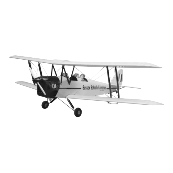
Length: 60" [1,524mm]
Weight: 10.25 lbs [4,592g]
Wingspan: 71" [1,803.4mm]
Wing Area: 1360 sq in [8,840 sq cm]
Wing Loading: 17.35 oz/sq ft [485.5 g/sq cm]
Radio: 4-ch (5 servos)
Engine: .61 two-stroke, .91 four-stroke [10cc 2-stroke, 15cc 4-stroke]
Great Planes
®
Model Manufacturing Co. guarantees this kit to be free from defects in both material and workmanship at the date of
purchase. This warranty does not cover any component parts damaged by use or modification. In no case shall Great Planes' liability
exceed the original cost of the purchased kit. Further, Great Planes reserves the right to change or modify this warranty without notice.
In that Great Planes has no control over the final assembly or material used for final assembly, no liability shall be assumed nor
accepted for any damage resulting from the use by the user of the final user-assembled product. By the act of using the user-assembled
product, the user accepts all resulting liability.
If the buyer is not prepared to accept the liability associated with the use of this product, the buyer is advised to return this
kit immediately in new and unused condition to the place of purchase.
READ THROUGH THIS MANUAL BEFORE
STARTING CONSTRUCTION. IT CONTAINS
IMPORTANT WARNINGS AND INSTRUCTIONS
CONCERNING THE ASSEMBLY AND USE OF
THIS MODEL.
© Copyright 2001
INSTRUCTION MANUAL
WARRANTY
1610 Interstate Drive, Champaign, IL 61822
(217) 398-8970, Ext 2
airsupport@greatplanes.com
GPMZ0231 for GPMA1330 V1.2
Advertisement
Table of Contents

Related Manuals for GREAT PLANES Tiger Moth ARF


Summary of Contents for GREAT PLANES Tiger Moth ARF
-
Page 1: Instruction Manual
READ THROUGH THIS MANUAL BEFORE STARTING CONSTRUCTION. IT CONTAINS IMPORTANT WARNINGS AND INSTRUCTIONS 1610 Interstate Drive, Champaign, IL 61822 CONCERNING THE ASSEMBLY AND USE OF (217) 398-8970, Ext 2 THIS MODEL. airsupport@greatplanes.com © Copyright 2001 GPMZ0231 for GPMA1330 V1.2... -
Page 2: Table Of Contents
Tiger Moth, visit the web site listed below and select the Install the Engine..............15 Great Planes Tiger Moth ARF. A “tech notice” box will appear in the upper left corner of the page if there is new technical Mount the Cowl ..............15 information or changes. -
Page 3: Decisions You Must Make
5. You must properly install all R/C and other components so The Tiger Moth qualifies as a "giant scale" model and is an that the model operates properly on the ground and in the air. excellent sport-scale model. It is therefore eligible to fly in IMAA events. -
Page 4: Covering Accessories
Curved Tip Canopy Scissors for Trimming Plastic Parts Covering Accessories (HCAR0667) Dead Center ™ Engine Mount Hole Locator (GPMR8130) Top Flite ® MonoKote ® sealing iron (TOPR2100) Great Planes Receiver Guard (GPMM1010) Top Flite MonoKote trim seal iron (TOPR2200) Great Planes AccuThrow ™... -
Page 5: Ordering Replacement Parts
ORDERING REPLACEMENT PARTS To order replacement parts for the Great Planes Tiger Moth ARF, use the order numbers in the Replacement Parts List that follows. Replacement parts are available only as listed. Not all parts are available separately (an aileron cannot be purchased separately, but is only available with the wing kit). -
Page 6: Kit Contents
Kit Contents list on this page. Great Planes Product Support: Phone: (217) 398-8970 Fax: (217) 398-7721 E-mail: airsupport@greatplanes.com Kit Contents (Photographed) 1. Top Wing 9. 3-1/4" Wheels (2) 17. Wind Screens (2) 2. -
Page 7: Preparations
PREPARATIONS ❏ 1. If you have not done so already, remove the major parts of the kit from the box (wings, fuse, cowl, tail parts, etc.) and inspect them for damage. If any parts are damaged or missing, contact Product Support at the address or telephone number listed on page 6. - Page 8 for proper function. Draw a line to the servo arm hole at 90-degrees from the aft edge of the aileron bay. At this location mark and drill the two 1/16" [1.6mm] holes into the bottom of the aileron for mounting the nylon control horn. Saturate the holes with thin CA, wipe away any residual CA and allow it to fully harden.
-
Page 9: Join The Wings
generous amount of epoxy into the inside of the wing joiner JOIN THE WINGS pocket. Important: Make sure the joiner is fitted upright to ensure the proper dihedral. Then, join the wing halves tightly, holding them together. Use a paper towel to wipe away excess epoxy that comes out of the wing.Tightly hold the wing together with masking tape, making certain both halves are in full contact and that the leading and trailing edges align. - Page 10 ❏ 9. Install four 90-degree metal brackets into the pre-drilled holes in the bottom of the top wing center section with 3mm x 12mm wood screws. ❏ 11. Locate the pre-drilled holes in the top of the bottom wing and install the four compound-bend metal brackets in place.
-
Page 11: Install Flying Wires
❏ 14. Attach the top wing center section by inserting two Install Flying Wires 4-40 x 3/4" [19mm] socket head cap screws with #4 washers through the 45-degree metal bracket, the rear cabane struts NOTE: The flying wires included with the Tiger Moth are and the 90-degree brackets. -
Page 12: Assemble The Fuselage
wires which run between the two interplane struts as shown in the photo. Cut two pieces of wire 11" [279mm] and make two wire assemblies, using the same process as above. These wires run from the bottom of the aft interplane strut to the top of the forward and from the bottom of the forward strut to the top of the aft strut, forming an X-brace between the forward and aft struts as shown in the previous photo. - Page 13 horizontal stab and just forward and aft of the opening, being careful not to cut into the wood. This will allow the fin to fit properly into place. ❏ 3. With the wings in place and the stab firmly taped, place the model in a building stand such as a Robart Super Stand II, (ROBP1402).
- Page 14 ❏ 10. Remove any pins you may have inserted into the hinges. Adjust the elevator so there is a small gap between the LE of the elevator and the stab. The gap should be small-just enough to see light through or to slip a piece of paper through. ❏...
-
Page 15: Install The Engine
Install the Engine Mount the Cowl Tick marks for alignment ❏ 1. Note: The proper thrust angle for the engine has been built-in. Find the location markings on the firewall and use a straight edge to draw lines between the horizontal and vertical marks. -
Page 16: Install The Fuel Tank
line may become stuck above the fuel level and stop the fuel flow. Remember (or use a felt-tip pen to mark) which tube is the fuel pick-up tube and which tube is the vent. ❏ 2. Install the tank into the fuse. Fit the neck through the hole in the firewall. - Page 17 ❏ 5. Install the rubber grommets and brass eyelets in the servos using the above sketch as a guide. Cut Off Unused Arms ❏ 6. Cut off three arms from three servo horns included with your radio control set to make them into “one arm” servo Correct Incorrect horns.
- Page 18 pack and receiver in at least 1/4" of R/C foam rubber (HCAQ1000) and mount them on balsa rails which can then be glued into the fuselage. On our model with an OS FS-91 II Surpass w/Pump (OSMG0890), the battery was mounted under the fuel tank as far forward as possible and the receiver as shown in the photo to minimize the amount of weight required to balance the model at the correct C.G.
-
Page 19: Install The Landing Gear
❏ ❏ 18. Drill a 3/16" hole through the firewall for the throttle 21. Set the carburetor to the closed position. Turn the pushrod guide tube. Be certain to not drill into the tank! It radio system on and move the throttle servo to the fully may be helpful to remove the engine for this step, so it does closed position. -
Page 20: Finishing Touches
❏ ❏ 2. Locate the landing gear fairings and trial fit around 3. As instructed before you will note that we painted the the landing gear wire as shown in the photo. When satisfied two cockpits flat black. We also placed a 1/4-scale Williams with the fit, glue them into place with 6-minute epoxy, joining Brothers Scale Pilot (WBRQ2625) inside the rear cockpit the halves as you do. -
Page 21: Set The Control Throws
These are the recommend control surface throws: 4-CHANNEL RADIO SETUP (STANDARD MODE 2) High Rate Low Rate ELEVATOR: 1" [25.4mm] up 3/4" [19.1mm] up 1" [25.4mm] down 3/4" [19.1mm] down ELEVATOR MOVES UP RUDDER: 2" [50.8mm] right 2" [50.8mm] right 4-CHANNEL TRANSMITTER 2"... -
Page 22: Balance The Model Laterally
PREFLIGHT 2-3/4" [70mm] Identify Your Model No matter if you fly at an AMA sanctioned R/C club site or if you fly somewhere on your own, you should always have your name, address, telephone number and AMA number on or inside your model. -
Page 23: Ground Check
Use a “chicken stick” or electric starter to start the engine. Ground Check Do not use your fingers to flip the propeller. Make certain the glow plug clip or connector is secure so that it will not pop If the engine is new, follow the engine manufacturer's off or otherwise get into the running propeller. -
Page 24: Check List
❏ 3. I will perform my initial turn after takeoff away from the pit 15. Make sure the fuel lines are connected and are not or spectator areas and I will not thereafter fly over pit or kinked. ❏ spectator areas, unless beyond my control. 16. -
Page 25: Takeoff
Takeoff Landing Before you get ready to takeoff, see how the model handles To initiate a landing approach, lower the throttle while on the on the ground by doing a few practice runs at low speeds downwind leg. Allow the nose of the model to pitch on the runway. - Page 26 The first ARF of the feared German fighter! Wingspan: 70 in Wing Area: 770 sq in Weight: 8 lb Wing Loading: 24 oz/sq ft Length: 55 in Requires: 2-stroke .61-.75 or 4-stroke .91 engine, 4-7 channel radio w/5-7 servos The fierce Luftwaffe Stuka dive-bomber struck fear into the hearts of Allied troops during WWII — and now it returns to the skies over your flying field! From the fiberglass cowl and wheel pants to its “underslung”...
- Page 27 O.S. ® .61 FX Engine You'll find many refinements on the high- Remote needle valve performance O.S. .61 FX engine. Features include makes adjustments a backplate-mounted needle for easy, safe mixture safe and easy! adjustments; advanced carb for precise air/fuel mixing;...
- Page 28 BUILDING NOTES Kit Purchased Date: _______________________ Date Construction Finished: _________________ Where Purchased:_________________________ Finished Weight: __________________________ Date Construction Started: __________________ Date of First Flight: ________________________ FLIGHT LOG...
Need help?
Do you have a question about the Tiger Moth ARF and is the answer not in the manual?
Questions and answers