Table of Contents
Advertisement
Quick Links
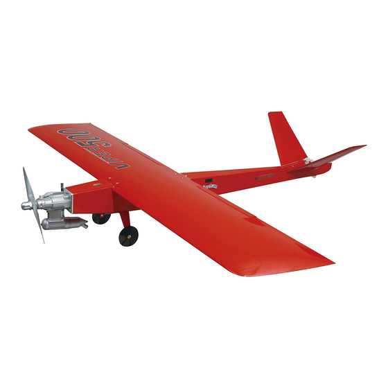
Wingspan: 52 in [1320mm]
Wing Area: 504 sq in [33dm²]
Weight: 3.5 lbs - 4 lbs [1360 - 1530g]
Wing Loading: 14 - 15 oz/sq ft [42 - 47 g/dm²]
Length: 41-1/4 in [1048mm]
Engine: .25 - .46 cu in [4.0 - 7.5cc] two-stroke
IMPORTANT NOTE: This model is designed for sport flying and AMA Quickie 500 racing. We will not quote all of the
AMA regulations for Quickie 500 racing in this manual. Any information provided here regarding racing is provided for
informational purposes only and is NOT guaranteed to be accurate. Only the printed version of the AMA regulations
should be used in case of protests or other disputes involving events covered by the regulations.
Great Planes
®
Model Manufacturing Co. guarantees this kit to be free from defects in both material and workmanship at the date of purchase.
This warranty does not cover any component parts damaged by use or modification. In no case shall Great Planes' liability exceed the
original cost of the purchased kit. Further, Great Planes reserves the right to change or modify this warranty without notice.
In that Great Planes has no control over the final assembly or material used for final assembly, no liability shall be assumed nor accepted for
any damage resulting from the use by the user of the final user-assembled product. By the act of using the user-assembled product, the user
accepts all resulting liability.
If the buyer is not prepared to accept the liability associated with the use of this product, the buyer is advised to return this kit
immediately in new and unused condition to the place of purchase.
READ THROUGH THIS MANUAL BEFORE STARTING
CONSTRUCTION.
INSTRUCTIONS AND WARNINGS CONCERNING THE
ASSEMBLY AND USE OF THIS MODEL.
GPMZ0203 for GPMA1265/1266 V1.0
INSTRUCTION MANUAL
IT
CONTAINS
WARRANTY
IMPORTANT
Champaign, IL
(217) 398-8970, Ext. 5
airsupport@greatplanes.com
Entire Contents © Copyright 2003
Advertisement
Table of Contents

Related Manuals for GREAT PLANES Viper 500 ARF


Summary of Contents for GREAT PLANES Viper 500 ARF
-
Page 1: Instruction Manual
Further, Great Planes reserves the right to change or modify this warranty without notice. In that Great Planes has no control over the final assembly or material used for final assembly, no liability shall be assumed nor accepted for any damage resulting from the use by the user of the final user-assembled product. -
Page 2: Table Of Contents
Set the Control Throws ..........18 Balance the Model (C.G.) ..........18 Balance the Model Laterally ........19 PREFLIGHT ..............19 1. Your Viper 500 ARF should not be considered a toy, but Identify Your Model.............19 rather a sophisticated, working model that functions very Charge the Batteries..........19 much like a full-size airplane. -
Page 3: Decisions You Must Make
If you have not flown this type of model before, we recommend that you get the assistance of an experienced The recommended engine size range for the Viper 500 ARF pilot in your R/C club for your first flights. If you’re not a is .25 to .46 cu in [4.0 –... -
Page 4: Optional Supplies & Tools
Do not discard the kit box! With minimal disassembly, the • Whenever the term glue is written you should rely upon Viper 500 ARF can be reinserted into its box for transport your experience to decide what type of glue to use. When a and even shipment to contests! specific type of adhesive works best for that step, the instructions will make a recommendation. -
Page 5: Ordering Replacement Parts
ORDERING REPLACEMENT PARTS To order replacement parts for the Great Planes Viper 500 ARF, use the order numbers in the Replacement Parts List that follows. Replacement parts are available only as listed. Not all parts are available separately (an aileron cannot be purchased separately, but is only available with the wing kit). -
Page 6: Kit Contents
If any parts are missing or are not of acceptable quality, or if you need assistance with assembly, contact Great Planes Product Support. When reporting defective or missing parts, use the part names exactly as they are written in the Kit Contents list on this page. -
Page 7: Building Instructions
BUILDING INSTRUCTIONS BUILD THE WING & TAIL Preparations Mount the Ailerons 1. If you have not yet done so already, remove the parts of the kit from the box and inspect them for damage. If any parts are damaged or missing, contact product support at the address or telephone number on page 6. -
Page 8: Install The Aileron Servo & Pushrods
with the hinges. The pin will keep the hinge centered. Remove the pins from the hinges. Adjust the ailerons so there is a small gap–just enough to see light through or to slip a piece of paper through. 7. Apply six drops of thin CA to the top and bottom of each hinge. -
Page 9: Assemble & Mount The V-Tail
5. Thread a clevis 20 full turns onto each of the 6" [150mm] pushrods. 6. Attach the clevises to the torque rod horns. With the 4. Stand two to three yards or meters behind the plane servo centered, the servo arm parallel to the LE of the wings and sight straight down the center of the fuse. -
Page 10: Final Assembly
horns. Mount the control horn using 2-56 x 3/8" [9.5mm] This bend is to make the pushrod move as freely as machine screws and the nylon backing plate on the bottoms possible in the pushrod tube. It may take several small of the ruddervators. - Page 11 2. Temporarily mount the engine to the backplate engine mount. Use a pushrod aligned with the carburetor arm to determine the location for drilling the hole through the engine mount. Mark the mount where the pushrod enters. 3. Remove the engine, and then drill a 3/16" [4.8mm] hole through the mount at the mark.
-
Page 12: Mount The Landing Gear
9. Arrange the stopper and tubes as shown and insert them into the tank. Tighten the screw to expand the stopper, thus sealing the tank. Be certain the fuel line weight (clunk) at the end of the fuel line inside the tank does not contact the rear of the tank. -
Page 13: Install The Radio
1. Trim the servo tray to fit your servos. 3. Remove the covering from the two tail-skid mounting holes on the bottom of the fuse. Enlarge the tail-skid mounting holes with a 1/8" [3mm] drill. Glue the nylon tail- skid in place with medium CA. 2. - Page 14 5. Attach your receiver and receiver battery to the top of the servo tray. Use 1/4" [6mm] foam to isolate vibration, and the included hook-and-loop material to hold them in place. 9. Remove the covering from the antenna tube exit at the Remove the receiver and receiver battery.
- Page 15 13. Slide the ruddervator pushrods into the pushrod tubes and connect the clevises to the control horns. Keeping the ruddervator centered, mark the pushrod where it crosses the center of the servo arm. 14. Detach the clevises from the ruddervators and slide the pushrods forward, lifting the front of the pushrods out of the servo opening.
-
Page 16: Optional Rudder Modifications
27. Center the carburetor barrel by moving the pushrod. With the throttle servo and barrel centered, tighten the 4-40 set screw. Adjust the servo throw so at high throttle the carburetor barrel is completely open. Adjust the transmitter so at low throttle the carburetor barrel is closed or slightly open. -
Page 17: Apply The Decals
12. Glue the tube to the fuse with thin CA. Allow the CA to cure and then cut off the excess tube. 13. Attach a small control horn (not included) to the rudder the same as was done with the ruddervators. Align the holes in the horn with the hinge line. -
Page 18: Get The Model Ready To Fly
At this stage the model should be in ready-to-fly condition Use a Great Planes AccuThrow (or a ruler) to accurately with all of the systems in place including the engine, landing measure and set the control throw of each control surface... -
Page 19: Balance The Model Laterally
AMA number a Great Planes CG Machine, or lift it at the balance point on or inside your model. It is required at all AMA R/C club you marked. -
Page 20: Balance The Propellers
We use a Top Flite Precision Magnetic Prop Balancer ™ the engine. (TOPQ5700) in the workshop and keep a Great Planes Fingertip Prop Balancer (GPMQ5000) in our flight box. Keep these items away from the prop: loose clothing, shirt sleeves, ties, scarfs, long hair or loose objects such as... -
Page 21: Ama Safety Code (Excerpt)
Fuelproof all areas exposed to fuel or exhaust AMA SAFETY CODE (excerpt) residue such as the tank compartment and underside of hatch, wing saddle area, etc. Check the C.G. according to the measurements Read and abide by the following Academy of Model provided in the manual. -
Page 22: Flying
FLYING CAUTION (THIS APPLIES TO ALL R/C AIRPLANES): If, while flying, you notice any unusual sounds, such as a low-pitched “buzz,” this may indicate control surface flutter . Because flutter can quickly destroy components of CAUTION SPECIFICALLY FOR QUICKIE 500 AND your airplane, any time you detect flutter you must OTHER RACE-STYLE AIRCRAFT: These models are immediately cut the throttle and land the airplane! Check... -
Page 23: Landing
Mind your fuel level, but use this first flight to become familiar with your model before landing. OTHER ITEMS AVAILABLE FROM REMEMBER to use high rates when practicing slow speed GREAT PLANES flight for sufficient control. Landing To initiate a landing approach, lower or “cut” the throttle while on the downwind leg. - Page 24 BUILDING NOTES Kit Purchased Date: _______________________ Date Construction Finished: _________________ Where Purchased:_________________________ Finished Weight: __________________________ Date Construction Started: __________________ Date of First Flight: ________________________ FLIGHT LOG...
Need help?
Do you have a question about the Viper 500 ARF and is the answer not in the manual?
Questions and answers