Table of Contents
Advertisement
Quick Links
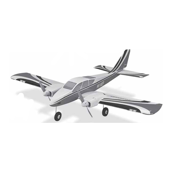
SPECIFICATIONS
Wingspan:
47.5 in [1205 mm]
Length:
42.5 in [1080 mm]
2
Wing Area:
392 in
[25.3 dm
WARRANTY
Great Planes
®
Model Manufacturing Co. guarantees this kit to
be free from defects in both material and workmanship at the
date of purchase. This warranty does not cover any component
parts damaged by use or modification. In no case shall Great
Planes' liability exceed the original cost of the purchased kit.
Further, Great Planes reserves the right to change or modify this
warranty without notice.
In that Great Planes has no control over the final assembly or
material used for final assembly, no liability shall be assumed nor
accepted for any damage resulting from the use by the user of
the final user-assembled product. By the act of using the
user-assembled product, the user accepts all resulting liability.
If the buyer is not prepared to accept the liability associated
with the use of this product, the buyer is advised to return
READ THROUGH THIS MANUAL BEFORE STARTING CONSTRUCTION. IT CONTAINS IMPORTANT
INSTRUCTIONS AND WARNINGS CONCERNING THE ASSEMBLY AND USE OF THIS MODEL.
© 2015 Great Planes Model Mfg. A subsidiary of Hobbico,
Weight:
4-4.25 lb
[1810-1930 g]
Wing
24-25 oz/ft
2
]
Loading:
[ 73-76 g /dm
®
Inc.
INSTRUCTION MANUAL
Radio:
2
Motor:
2
]
this kit immediately in new and unused condition to the
place of purchase.
To make a warranty claim send the defective part or item to
Hobby Services at the address below:
3002 N. Apollo Dr. Suite 1
Champaign IL 61822 USA
Include a letter stating your name, return shipping address, as
much contact information as possible (daytime telephone
number, fax number, e-mail address), a detailed description of
the problem and a photocopy of the purchase receipt. Upon
receipt of the package the problem will be evaluated as quickly
as possible.
airsupport@greatplanes.com
4-channel minimum with 4 servos
and standard size receiver
RimFire .10 (35-30-1250) x 2
Hobby Services
Champaign, Illinois
(217) 398-8970, Ext 5
GPMA1609 v1.1
Advertisement
Table of Contents

Related Manuals for GREAT PLANES TWINSTAR EP


Summary of Contents for GREAT PLANES TWINSTAR EP
-
Page 1: Instruction Manual
3002 N. Apollo Dr. Suite 1 Champaign IL 61822 USA In that Great Planes has no control over the final assembly or material used for final assembly, no liability shall be assumed nor Include a letter stating your name, return shipping address, as... -
Page 2: Table Of Contents
It even applies to fl ying at public demonstrations and air shows. Failure to 2. Your Twinstar EP should not be considered a toy, but rather comply with the Safety Code (excerpts printed in the back of a sophisticated, working model that functions very much like the manual) may endanger insurance coverage. -
Page 3: Safety Precautions
DECISIONS YOU MUST MAKE GPMR6047) Threadlocker thread locking cement (GPMR6060) This is a partial list of items required to fi nish the Twinstar EP Denatured alcohol (for epoxy clean up) that may require planning or decision making before starting Drill bits: 1/16" [1.6mm], 5/64" [2mm] to build. -
Page 4: Optional Supplies And Tools
Fax: (217) 398-7721 E-mail: airsupport@greatplanes.com ORDERING REPLACEMENT PARTS Replacement parts for the Great Planes Twinstar EP ARF are available using the order numbers in the Replacement Parts A building stand or cradle comes in handy during the build. List that follows. The fastest, most economical service can We use the Robart Super Stand II (ROBP1402) for all our be provided by your hobby dealer or mail-order company. -
Page 5: Kit Contents
Follow the instructions provided on the page to locate a U.S., Canadian or International dealer. GPMA4390 WING SET TWINSTAR EP ARF GPMA4391 FUSELAGE TWINSTAR EP ARF Parts may also be ordered directly from Hobby Services by... -
Page 6: Preparations
PREPARATIONS 1. If you have not done so already, remove the major parts of the kit from the box and inspect for damage. If any parts are damaged or missing, contact Product Support at the address or telephone number listed in the “Kit Inspection” section on page 4. - Page 7 their best orientation so that the arms are closest to being perpendicular with the servo case. Cut three arms from each servo arm leaving one arm on each servo that matches the photo. Enlarge the hole closest to 9/16" [14.3 mm] to the center of the servo arm of each remaining arm with a 5/64"...
- Page 8 pushrods to the outer holes of the control horns. Position the control horns over the hardwood plates in the ailerons (if you cannot see them, hold the aileron at a shallow angle in good lighting or use a small pin to puncture the covering) being sure the pushrods are lined up with the enlarged holes in the aileron servo arms.
- Page 9 11. Install the aluminum X-mount onto the motors using the screws included with the motors and thread locking compound. Install the prop adapters using the screws included with the motors and thread locking compound. 12. Mount the motors to the nacelle fi rewalls using 3 x12 mm machine screws, 3mm fl at washers, and thread locking compound.
- Page 10 14. Connect an ESC to the battery Y-harness end you 13. Feed one of the female ends of the battery Y-harness inserted through the wing. Use one of the included tie through the forward wing sheeting hole in one wing panel. straps to secure the connectors together as shown.
- Page 11 Y-harness and secure it with a tie strap. Look ahead to the photo in step 16 and feed the ESC receiver leads through the same holes as the battery harness and the aileron servo leads through the aft wing sheeting holes. 16.
-
Page 12: Assemble The Fuselage
position of each collar onto the axle. Grind a fl at spot onto the axle for each wheel collar set screw (look at the fl at spots on the nose gear for an example). Install the wheel collars and wheels back onto the axles and secure the collars with 3mm set screws and thread locking compound. - Page 13 5. Re-insert the horizontal stabilizer and vertical fi n into the fuse. With the wing in place, stand behind the model approximately 10 feet [3m] and confi rm that the stab sits parallel with the wing. If not, weight can be added to the high side while gluing the stab in place, or the stab pocket can be lightly sanded until the stab and wing sit parallel.
- Page 14 6. Thread a nylon clevis onto a 27" [685 mm] pushrod. Attach the clevis to a control horn and slide the pushrod into the outer pushrod tube on the right side of the fuse. As you did with the ailerons, align the control horn over the elevator hinge line and mark the location of the screw holes.
- Page 15 12. Cut the included 4" [100 mm] length of white tube into 10. Mix up a small batch of epoxy and apply a thin coat to two equal pieces. Use CA to glue the pieces 90 degrees to the battery tray and the side of the fuselage by the elevator each other near the receiver.
- Page 16 RTV silicone. operation of the motors, install the propellers and spinners onto the motor shafts. 16. Congratulations on the completion of the Twinstar EP! Now it’s time to put on the decals, balance the plane and confi rm the control throws.
-
Page 17: Apply The Decals
Reinstall the screws that hold on the servo arms. Use a Great Planes AccuThrow (or a ruler) to accurately 3. With the transmitter still on and the fl ight battery plugged measure and set the control throw of each control surface in, check all the control surfaces to see if they are centered. -
Page 18: Balance The Model (C.g.)
11° 21° Preferred Pushrod Hookup IMPORTANT: The Twinstar EP has been extensively fl own and tested to arrive at the throws at which it fl ies best. Flying your model at these throws will provide you with the greatest chance for successful fi rst fl ights. If, after... -
Page 19: Balance The Model Laterally
We use a Top Flite Precision Magnetic Prop Balancer Balance the Model Laterally (TOPQ5700) in the workshop and keep a Great Planes Fingertip Prop Balancer (GPMQ5000) in our fl ight box. 1. With the wing level, have an assistant help you lift the... -
Page 20: Motor Safety Precautions
your model and, while you work the controls, tell you what the 7) I will not operate models with pyrotechnics (any device that explodes, burns, or propels a projectile of any kind). control surfaces are doing. Repeat this test with the motor running at various speeds with an assistant holding the model, using hand signals to show you what is happening. -
Page 21: Flying
The Twinstar EP ARF is a great-fl ying model that fl ies smoothly Add power to see how the model climbs as well. Continue to and predictably. -
Page 22: Landing
One fi nal note about fl ying your model. Have a goal or fl ight Landing plan in mind for every fl ight. This can be learning a new maneuver(s), improving a maneuver(s) you already know, or To initiate a landing approach, lower the throttle while on the learning how the model behaves in certain conditions (such as downwind leg. - Page 24 Entire Contents © 2015 Great Planes Model Mfg. A subsidiary of Hobbico, Inc. GPMA1609 v1.1...
Need help?
Do you have a question about the TWINSTAR EP and is the answer not in the manual?
Questions and answers