Icom IC-M87 Instruction Manual
Vhf marine transceiver
Hide thumbs
Also See for IC-M87:
- Instruction manual (48 pages) ,
- Service manual (42 pages) ,
- Instruction manual (10 pages)
Table of Contents
Advertisement
Quick Links
Download this manual
See also:
Instruction Manual
Advertisement
Table of Contents

Subscribe to Our Youtube Channel
Related Manuals for Icom IC-M87


Summary of Contents for Icom IC-M87
- Page 1 INSTRUCTION MANUAL VHF MARINE TRANSCEIVER iM87...
-
Page 2: Recommendation
IN CASE OF EMERGENCY RECOMMENDATION CLEAN THE TRANSCEIVER THOROUGHLY WITH FRESH If your vessel requires assistance, contact other vessels and the Coast Guard by sending a distress call on Channel 16. WATER after exposure to saltwater. Otherwise, the transceiv- er’s keys, switches and controllers may become inoperable due to salt crystallization. -
Page 3: Foreword
FOREWORD FEATURES ☞ 22 free channels for PMR use Thank you for purchasing this Icom product. The IC-M87 VHF MARINE TRANSCEIVER is designed and built with Icom’s state The IC-M87 has 22 free channels reserved for PMR use of the art technology and craftsmanship. With proper care this (146–174MHz). -
Page 4: Precaution
DO NOT Icom optional equipment is designed for optimal performance use or place the transceiver in direct sunlight when used with this transceiver. We are not responsible for or in areas with temperatures below –15°C or above +55°C:... -
Page 5: Table Of Contents
TABLE OF CONTENTS IN CASE OF EMERGENCY ..........i 6 DUALWATCH/TRI-WATCH ..........15 RECOMMENDATION ............i ■ Description ..............15 FOREWORD ................ ii ■ Operation..............15 IMPORTANT ................. ii 7 LAND (PMR) CHANNEL OPERATION ......16 EXPLICIT DEFINITIONS ............ii ■ LAND (PMR) Channel Group ........16 FEATURES ................ -
Page 6: Intrinsic Safety
BP-227AX clean to avoid any risk of ignition due to the build-up of electrostatic charges. Repair of Icom radios should only be carried out by au- thorized Icom distributors. In particular, repair of ATEX ap- ONLY... -
Page 7: Operating Rules
OPERATING RULES D Priorities (2) OPERATOR’S LICENSE A restricted Radiotelephone Operator Permit is the license • Read all rules and regulations pertaining to priorities and most often held by small vessel radio operators when a radio keep an up-to-date copy handy. Safety and distress calls is not required for safety purposes. -
Page 8: Supplied Accessaries And Attachments
SUPPLIED ACCESSARIES AND ATTACHMENTS Supplied accessories w Clip the belt clip to a part of your belt and insert the stop- per to the belt clip. The following accessories are supplied: Qty. • Swivel belt clip ....... . . 1 •... -
Page 9: Supplied Accessaries And Attachments
SUPPLIED ACCESSARIES AND ATTACHMENTS Flexible antenna To remove: Turn the transceiver upside down, and then lift up to release Connect the supplied flexible antenna the transceiver from the belt clip. to the antenna connector. CAUTION! • NEVER carry the transceiver by holding the antenna. -
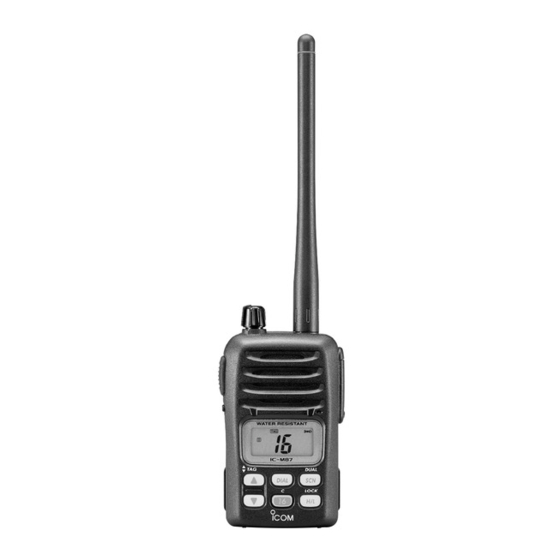
Page 10: Panel Description
PANEL DESCRIPTION ■ Front, top and side panels q VOLUME CONTROL [VOL] Turns power ON and adjusts the audio level. w ANTENNA CONNECTOR (p. 3) Connects the supplied antenna. e SPEAKER-MICROPHONE CONNECTOR [SP MIC] (p. 26) Connects the optional speaker-microphone. [SP MIC] jack cover NOTE: KEEP the [SP MIC] jack cover attached to the... - Page 11 PANEL DESCRIPTION ï BATTERY PACK RELEASE BUTTON u CHANNEL UP/DOWN SWITCHES [Y]/[Z] To release the battery pack: • Select an operating channel. (p. 9) Push the battery release button in the direction of the arrow • Selects the set mode condition of item. (p. 17) (q) as shown below.
-
Page 12: Function Display
PANEL DESCRIPTION ■ Function display e TAG CHANNEL INDICATOR (p. 14) Appears when a TAG channel is selected. r SCAN INDICATOR (p. 14) Blinks while scanning. t LOCK INDICATOR (p. 11) Appears while the lock function is activated. y NARROW INDICATOR (p. 16) Appears when narrow channel spacing is selected. -
Page 13: Panel Description
PANEL DESCRIPTION i DUALWATCH/TRI-WATCH INDICATORS (p. 15) !4 CHANNEL GROUP INDICATOR (pgs. 9, 16) “DUAL” appears during Dualwatch; “TRI” appears during “I” appears when International; “U” appears when U.S.A. Tri-watch. (U.K. version only); “ ” appears when LAND (PMR) channel group is selected. “ATIS” appears when the chan- o SCRAMBLER INDICATOR nel group in which ATIS function is activated. -
Page 14: Basic Operation
BASIC OPERATION ■ Channel selection IMPORTANT: Prior to using the transceiver for the first D Call channel time, the battery pack must be fully charged for optimum Each regular channel group has a separate call channel. In life and operation. To avoid damage to the transceiver, turn addition, each call channel is monitored during Tri-watch. - Page 15 BASIC OPERATION D International, U.S.A and ATIS* channels There are 57 International, 58 U.S.A. and 57 ATIS* channels. These channel groups may be specified for the operating area. q Push [DIAL] to select a regular channel. Push Push International channels w Push [Y]/[Z] to select a channel.
-
Page 16: Receiving And Transmitting
BASIC OPERATION ■ Receiving and transmitting IMPORTANT: To maximize the readability of your transmit- ted signal, pause a few sec. after pushing [PTT], hold the microphone 5 to 10 cm from your mouth and speak at a CAUTION! Transmitting without an antenna may damage normal voice level. -
Page 17: Adjusting The Squelch Level
■ Adjusting the squelch level ■ Lock function The IC-M87 has a squelch even though there is no control This function electronically locks all keys (except for [PTT], knob for it. In order to receive signals properly, as well as for [SQL] and [H/L•... -
Page 18: Call Channel Programming
BASIC OPERATION ■ Call channel programming ■ Voice scrambler operation D Activating the scrambler Call channel is used to access Channel 16 (default; may differ according to version), however, you can program the The optional voice scrambler provides private communica- call channel with your most often-used channels in each tions. -
Page 19: Scan Operation
SCAN OPERATION ■ Scan types Set the TAG channels (scanned channel) before scanning. Scanning is an efficient way to locate signals quickly over a Clear the TAG for unwanted channels which inconveniently wide frequency range. The transceiver has priority scan and stop scanning, such as those for digital communications. -
Page 20: Setting Tag Channels
SCAN OPERATION ■ Setting TAG channels ■ Starting a scan For more efficient scanning, add desired channels as TAG Set the priority scan function, scan resume timer and auto channels or clear TAG channels for unwanted channels. scan function in advance, using set mode. (p. 18) Channels that are not tagged will be skipped during scan- ning. -
Page 21: Dualwatch/Tri-Watch
DUALWATCH/TRI-WATCH ■ Description ■ Operation Dualwatch monitors Channel 16 while you are receiving an- q Select Dualwatch or Tri-watch in the set mode. (p. 19) other channel; Tri-watch monitors Channel 16 and the call w Select the desired operating channel. channel while receiving another channel. -
Page 22: Land (Pmr) Channel Operation
The default setting of the LAND channel group is the same as that of the INT channel group. Ask your local Icom dealer for the LAND channel group setting and PMR frequency pro- gramming details. -
Page 23: Set Mode
SET MODE ■ Set mode programming D SET mode operation set mode is used to change the condition of 12 transceiver functions: Beep tone function, Priority scan function, Scan q Turn power OFF. resume timer, Auto scan function, Dualwatch/Tri-watch w W hile pushing [SQL], turn power ON to enter set mode. function, Monitor switch action, Automatic backlighting, LCD •... -
Page 24: Set Mode Items
SET MODE ■ Set mode items D Beep tone function “bP” D Scan resume timer “St” The scan resume timer can be set as a pause (OFF) or timer You can select silent operation by turning the beep tones scan (ON). OFF, or you can have 2 types of confirmation beeps sound •... - Page 25 SET MODE D Dual/Tri-watch function “dt” D Automatic backlighting “bL” This item selects Dualwatch or Tri-watch as desired. See p. This function is convenient for nighttime operation. The au- 14 for details. tomatic backlighting can be adjusted from OFF, 1 (dark)–3 (bright);...
- Page 26 SET MODE D Auto power save function “PS” D Self check function “SC” The auto power save function reduces current drain by deac- The self check function checks transceiver conditions by it- tivating the receiver circuit for preset intervals. self, and informs you in case a problem is found. The follow- •...
-
Page 27: Set Mode
SET MODE D Battery voltage indicator “bt” SET MODE LIST This function contains display or non-display settings of the Function Indication Switch voltage of the connected battery pack when the power is Beep tone function “bP” OFF / ON* / US •... -
Page 28: Battery Charging
BATTERY CHARGING ■ Battery charging ■ Cautions NEVER Prior to using the transceiver for the first time, the battery incinerate used battery packs. Internal battery gas pack must be fully charged for optimum life and operation. may cause an explosion. NEVER immerse the battery pack in water. -
Page 29: Charging Connections
Turn power OFF Transceiver to secure the trans- Battery pack ceiver, if desired. Ensure sides of the battery pack correctly aligned with the charger groves. Charge indicator lights green when BP-227AX (with/ without IC-M87) is inserted. Supplied screws BC-152 AC adapter... -
Page 30: Ad-100 Installation
BATTERY CHARGING ■ AD-100 installation ➥ Connect the AD-100 and the BC-119N/ The AD-100 must be installed into the BC- charger adapter charger adapter BC-121N as below (q), then install the AD-100 into the 119N or BC-121N before battery charging. holder space of the BC-119N or BC-121N with the sup- plied screws (w). -
Page 31: Optional Battery Chargers
BATTERY CHARGING ■ Optional battery chargers D Rapid charging with the BC-121N+AD-100 D Rapid charging with the BC-119N+AD-100 The optional BC-121N allows up to 6 battery packs to be The optional BC-119N provides rapid charging of battery charged simultaneously. The following are additionally re- packs. -
Page 32: Speaker-Microphone
SPEAKER-MICROPHONE ■ HM-138 Description ■ Attachments Insert the connector of the speaker-microphone into the [SP MIC] connector on the transceiver and tighten the screw. Alligator type clip To attach the speaker-mic. to your shirt or collar, etc. Detaching: Unscrew (q), then detach the PTT switch jack cover (w). -
Page 33: Troubleshooting
TROUBLESHOOTING PROBLEM POSSIBLE CAUSE SOLUTION REF. The transceiver does • The battery is exhausted. • Recharge the battery pack. p. 22 not turn ON. • Bad connection to the battery pack. • Check the connection to the transceiver. p. 5 No sound from speaker. -
Page 34: Vhf Marine Channel List
VHF MARINE CHANNEL LIST • International channels Frequency (MHz) Frequency (MHz) Frequency (MHz) Frequency (MHz) Frequency (MHz) Frequency (MHz) Transmit Receive Transmit Receive Transmit Receive Transmit Receive Transmit Receive Transmit Receive 156.050 160.650 156.550 156.550 157.050 161.650 156.075 160.675 156.575 156.575 157.075 161.675... -
Page 35: Specifications
SPECIFICATIONS GENERAL • Max. frequency deviation • Frequency coverage Marine : ±5 kHz (Wide) Marine : 156.000–161.450 MHz : ±5 kHz (Wide) : 156.000–163.425 MHz ±4 kHz (Wide) <German ver.> TX/RX : 146.000–174.000 MHz ±2.5 kHz (Narrow) • Audio harmonics distortion : Less than 10% (at 60% mod.) •... -
Page 36: Options
OPTIONS • BP-227AX • HM-138 i on battery pack speaker microphone 7.2 V/1700 mAh Li-Ion battery pack. The same as supplied Full-sized waterproof speaker-microphone including alliga- with the transceiver. BP-227AX must be charged with the tor type clip to attach to your shirt or collar, etc. supplied BC-152 or the optional BC-119N/121N. -
Page 37: Quick Reference
QUICK REFERENCE Important operating instructions are summed up in this and the following page for your simple reference. By cutting along the line and folding on the dotted line, it will become a card sized operating guide which can easily be carried in a card case or wallet, etc. -
Page 38: Doc
The following explanations are about the symbols on the at- tached Declaration of Conformity. CE Versions of the IC-M87 which display the “CE” symbol on the serial number seal, comply with the essential requirements of the European Radio and Telecommunication Terminal Directive 1999/5/EC and ATEX Directive 94/9/EC. -
Page 39: Atex Cautions
D Special conditions for safe use The equipment is an intrinsically safe equipment. It can be used in a potentially explosive atmosphere. The equipment must be powered only by the battery Icom type BP-227AX. When the transceiver is used in a hazardous areas, either the jack cover or HM-138 must be attached to the connector. - Page 40 < Intended Country of Use > A-6409H-1EU-r Printed in Japan © 2005–2008 Icom Inc. 1-1-32 Kamiminami, Hirano-ku, Osaka 547-0003, Japan Printed on recycled paper with soy ink.
Need help?
Do you have a question about the IC-M87 and is the answer not in the manual?
Questions and answers