Icom IC-M87 Instruction Manual
Hide thumbs
Also See for IC-M87:
- Instruction manual (48 pages) ,
- Service manual (42 pages) ,
- Instruction manual (40 pages)
Advertisement
Quick Links
Advertisement

Subscribe to Our Youtube Channel
Related Manuals for Icom IC-M87


Summary of Contents for Icom IC-M87
- Page 1 INSTRUCTION MANUAL VHF MARINE TRANSCEIVER iM87...
- Page 2 IN CASE OF EMERGENCY RECOMMENDATION If your vessel requires assistance, contact other vessels and CLEAN THE TRANSCEIVER THOROUGHLY WITH FRESH WATER after exposure to saltwater, and dry it before opera- the Coast Guard by sending a distress call on Channel 16. tion.
- Page 3 FOREWORD FEATURES ☞ 22 free channels for PMR use Thank you for purchasing this Icom product. The IC-M87 VHF MARINE TRANSCEIVER is designed and built with Icom’s state The IC-M87 has 22 free channels reserved for PMR use of the art technology and craftsmanship. With proper care this (146–174MHz).
- Page 4 0.9 meter away from your vessel’s magnetic navigation compass. Icom, Icom Inc. and Icom logo are registered trademarks of Icom Incorpo- rated (Japan) in Japan, the United States, United Kingdom, Germany, France, Spain, Russia and/or other countries.
- Page 5 TABLE OF CONTENTS 6 DUALWATCH/TRI-WATCH ............15 IN CASE OF EMERGENCY .............. i RECOMMENDATION ................ i ■ Description ................15 FOREWORD ..................ii ■ Operation ................15 IMPORTANT ..................ii 7 LAND (PMR) CHANNEL OPERATION ........16 EXPLICIT DEFINITIONS ..............ii ■ LAND (PMR) Channel Group ..........16 FEATURES ..................
- Page 6 OPERATING RULES D Priorities (2) OPERATOR’S LICENSE A restricted Radiotelephone Operator Permit is the license • Read all rules and regulations pertaining to priorities and most often held by small vessel radio operators when a radio keep an up-to-date copy handy. Safety and distress calls is not required for safety purposes.
- Page 7 SUPPLIED ACCESSORIES AND ATTACHMENTS Supplied accessories w Clip the belt clip to a part of your belt and insert the stop- per to the belt clip. The following accessories are supplied: Qty. • Swivel belt clip ........1 •...
- Page 8 SUPPLIED ACCESSORIES AND ATTACHMENTS Flexible antenna To remove: Turn the transceiver upside down, and then lift up to release Connect the supplied flexible antenna the transceiver from the belt clip. to the antenna connector. CAUTION: • Transmitting without an antenna may damage the transceiver.
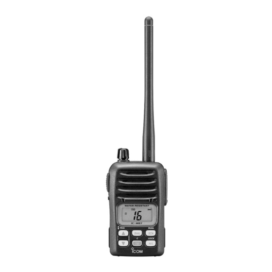
- Page 9 PANEL DESCRIPTION ■ Front, top and side panels q VOLUME CONTROL [VOL] Turns power ON and adjusts the audio level. w ANTENNA CONNECTOR (p. 3) Connects the supplied antenna. e SPEAKER-MICROPHONE CONNECTOR [SP MIC] (p. 27) Connects the optional speaker-microphone. [SP MIC] jack cover NOTE: KEEP the [SP MIC] jack cover attached to the transceiver when the...
- Page 10 < Intended Country of Use > A-6215H-1EU-y Printed in Japan © 2002–2012 Icom Inc. 1-1-32 Kamiminami, Hirano-ku, Osaka 547-0003, Japan Printed on recycled paper with soy ink.
Need help?
Do you have a question about the IC-M87 and is the answer not in the manual?
Questions and answers