Table of Contents
Advertisement
Quick Links
WARNING
FIRE OR EXPLOSION HAZARD
Failure to follow safety warnings exactly could result in serious
injury, death, or property damage.
- Do not store or use gasoline or other flammable vapors and liquids in the vicinity of this or any other
appliance.
- WHAT TO DO IF YOU SMELL GAS
•
Do not try to light any appliance.
• Do not touch any electrical switch: do not use any phone in your building.
Leave the building immediately.
• Immediately call your gas supplier from a neighbour's phone. Follow the gas supplier's
instructions.
• If you cannot reach you gas supplier, call the fire department.
- Installation and service must be performed by a qualified installer, service agency or the gas supplier.
Tested by:
919-379
REGENCY FIREPLACE PRODUCTS INTERNATIONAL LTD. 6988 Venture St., Delta, BC, Canada V4G 1H4
E33 Gas Insert
MODELS:
E33-NG10 Natural Gas
Owners & Installation Manual
Installer: Please complete the details on the back cover
and leave this manual with the homeowner.
Homeowner: Please keep these instructions for future reference.
E33-LP10 Propane
11.03.14
Advertisement
Table of Contents

Related Manuals for Regency Fireplace Products E33-NG10


Summary of Contents for Regency Fireplace Products E33-NG10
- Page 1 Tested by: Installer: Please complete the details on the back cover and leave this manual with the homeowner. Homeowner: Please keep these instructions for future reference. 919-379 REGENCY FIREPLACE PRODUCTS INTERNATIONAL LTD. 6988 Venture St., Delta, BC, Canada V4G 1H4 11.03.14...
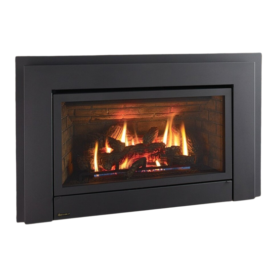
- Page 2 The E33 Gas Insert has been designed to provide you with all the warmth and charm of a fireplace, at the flick of a switch. The E33-NG10 and E33-LP10 have been approved by Warnock Hersey/Intertek for both safety and efficiency. As it also bears our own mark, it promises to provide you with economy, comfort and security for many trouble free years to follow.
-
Page 3: Dimensions
dimensions 32-1/4” 819mm 24-1/2” (622mm) optional spacer " (83mm) 2 " " (1181mm) (44mm) 16 " (1078mm) (281mm) 4 " (413mm) Oversized Faceplate Dimensions" 49-9/16" x 33-1/8" H E33-10 FPI Direct Vent Gas Insert... -
Page 4: Table Of Contents
table of contents Dimensions ..............3 Safety Decal ..............5 MA Code - CO Detector..........6 Important Message ............7 For Your Safety ..............7 Before You Start ............7 Gas Pressure Testing ............8 Specifications ..............8 Installation Into A Solid Fuel Burning Fireplace Or Factory Built Fireplace ..........8 Installation Checklist .............8 Materials Required ............8 Gas Insert Aeration System ...........9... -
Page 5: Safety Decal
ANSI Z21.88-20 14 & CSA 2.33-20 4001172 Serial No. / No de serie NATURAL GAS FIREPLACE INSERT: MODEL E33-NG10 É QUIP A L'UISINE POUR GAZ NATURAL É Factory Equipped For Altitude 0-4500ft. (0-1370m) Pression d'allimentation minimum Min. Supply Pressure 5“... -
Page 6: Ma Code - Co Detector
requirements MA Code - CO Detector (for the State of Massachusetts only) 5.08: Modifications to NFPA-54, Chapter 10 (2) Revise 10.8.3 by adding the following additional requirements: (a) For all side wall horizontally vented gas fueled equipment installed in every dwelling, building or structure used in whole or in part for residential purposes, including those owned or operated by the Commonwealth and where the side wall exhaust vent termination is less than seven (7) feet above finished grade in the area of the venting, including but not limited to decks and porches, the following requirements shall be satisfied:... -
Page 7: Important Message
installation Fuel Gas Code ANSI Z223.1 in the U.S.A. This IMPORTANT MESSAGE appliance should be installed by a qualified gas CHILDREN AND ADULTS SHOULD BE SAVE THESE fitter technician only. ALERTED TO THE HAZARDS OF HIGH SURFACE TEMPERATURES, ESPE- INSTRUCTIONS 2) Installation and repair should be done by a CIALLY THE FIREPLACE GLASS, AND qualified service person. -
Page 8: Gas Pressure Testing
installation GAS PRESSURE insulation after the gas supply line has been "WARNING: This fireplace has been TESTING installed. converted for use with a gas fireplace insert only and cannot be used for burning wood or The fireplace and fireplace chimney must solid fuels unless all original parts have been The appliance must be isolated from the gas supply be clean and in good working order and... -
Page 9: Gas Insert Aeration System
installation MINIMUM FIREPLACE GAS INSERT OPENING AERATION SYSTEM The minimum fireplace opening for the Regency The air shutter can be adjusted by moving the gas fireplace insert when using the supplied spacer adjusting wire up or down. The wire is accessed is shown in the following diagrams: through the bottom louver opening. -
Page 10: Minimum Clearances To Combustibles
installation MINIMUM CLEARANCES TO COMBUSTIBLES From Unit Side Walls * A 8" (203 mm) Ceiling B 47" (1194 mm) Min. Mantel Height C 15" (381 mm) Max. Mantel Depth D 12" (305 mm) Alcove Width E 76" (1930 mm) Alcove Depth 36"... -
Page 11: Gas Connection
installation GAS CONNECTION In areas of consistently high winds, we recommend GAS CONNECTION using the Simpson Dura-Vent System (46dva-GK adapter and 46dva-VCH high-wind cap). WARNING: Only persons licensed to work The Air Intake pipe must be attached to the inlet air with gas piping may make the collar of the termination cap. -
Page 12: Remote Receiver Installation
installation REMOTE RECEIVER INSTALLATION DC SPARK IGNITER BATTERY INSTALLATION 1) Install the heat shield to the receiver with two screws. Install the supplied battery into the DC Sparker Box by opening the battery compartment. NOTE: The battery in the DC Sparker Box will need to be replaced annually. -
Page 13: Brick Panel Installation
installation BRICK PANEL INSTALLATION 6) Slide the top panel and bracket assembly 9) Insert the side panel by positioning it flat carefully onto the baffle plate ensuring the against the side walls. Tilt the panel panel is centered. Make sure the tabs of the towards the middle of the firebox, then insert 1) Remove safety screen and glass door if top bracket fit into the baffle openings (refer to... -
Page 14: Log Set Installation
DIRECT VENT FIREPLACE installation LOG SET INSTALLATION LOG INSTALLATION WARNING: 3) Remove the grate by removing the two Phillips Dangerous operating conditions may occur if these screws. Slide the grate outwards to remove it from logs are not positioned in their correct certifi ed loca- the unit (refer to Diagram 1). - Page 15 DIRECT VENT FIREPLACE installation 7) Align the bottom grooves of log 03-21 onto the right side of the grate and gently slide the log back until it touches the locating tab (refer to Diagram 4 & 5). 03-23 03-21 03-21 03-17 Locating Diagram 7...
- Page 16 DIRECT VENT FIREPLACE installation 12) Place log 03-19 over the left center of the grate. Ensure the log set looks like Diagram 12. 03-23 03-18 03-22 03-20 03-17 Diagram 10 03-19 Diagram 12 11) Place log 03-24 over log 03-23 and log 03-21 ensuring the pin hole of log 03-24 lines up with the right pin of log 03-23 and the right pin of log 03-21 13) Separate platinum embers and place at the front...
-
Page 17: Conversion From Ng To Lp
E33-10 installation Conversion from NG to LP CONVERSION KIT 342-969 FROM NG TO LP for E33-10 using SIT 829 NOVA Gas Valve for E33-10 using SIT 829 NOVA Gas Valve THIS CONVERSION MUST BE DONE BY A QUALIFIED GAS FITTER IF IN DOUBT DO NOT DO THIS CONVERSION !! THIS CONVERSION MUST BE DONE BY A QUALIFIED GAS FITTER IF IN DOUBT DO NOT DO THIS CONVERSION !! 7. Unscrew the pilot orifice with the 5/32"... -
Page 18: Low Profile Faceplate Installation
installation LOW PROFILE FACEPLATE INSTALLATION Low profi le faceplate installation A spacer is supplied and may be installed if required to extend the 3. Tuck the wires into the clip to keep them away from the insert using depth of the faceplate by 1-3/4". Install the spacer onto the back the clip provided. - Page 19 installation Attach the 2 bottom louver hinges to the bottom fl ange on the 11. Run the power cord out on the left side of the unit. fi rebox using 2 screws per hinge. 12. Line up the brackets on the outer faceplate with the slots on the faceplate backing–hook outer faceplate on to slots and lower to install.
-
Page 20: Optional Backing Plate Installation
installation Optional Backing plate installation OPTIONAL BACKING PLATE INSTALLATION Backing plate installation with spacer Backing plate installation without spacer 1. Install the spacer to the back of the faceplate backing with 6 screws 1. Secure the faceplate backing to the backing plate with 6 screws in from the front of the faceplate backing. -
Page 21: Safety Screen Installation
installation SAFETY SCREEN INSTALLATION 1. To remove safety screen, flip open bottom louver and remove 2 screws 2. Pull off safety screen and frame from glass door. in locations shown below. 3. To install, reverse Steps 2-1. STANDARD FLUSH DOOR The standard flush door comes with a black frame. -
Page 22: Wiring Diagram
installation WIRING DIAGRAM This heater does not require a 120V A.C. supply Caution: Ensure that WARNING: Electrical Grounding Instructions for operation. However, a 120V A.C. power the wires do not touch This appliance is equipped with a three pronged supply is needed for the fan/blower operation. any hot surfaces and (grounding) plug for your protection against shock are away from sharp... -
Page 23: First Fire
operating instructions FIRST FIRE 8) The unit should never be turned off, and on again without a minimum of a 60 second wait. 5. Press and release the ON/OFF button on the remote handheld transmitter. An audible beep The first fire in your stove is part of the paint curing 9) Hook up remote receiver to wire marked 'receiver' should be heard from the receiver. -
Page 24: Copy Of Lighting Instruction Plate
operating instructions AUTOMATIC COPY OF LIGHTING INSTRUCTION PLATE CONVECTION FAN OPERATION FOR YOUR SAFETY READ BEFORE LIGHTING This appliance must be installed in accordance with local codes, if any; The fan operates automatically. Turn the knob on if none, follow the National Fuel Gas Code, ANSI Z223.1/NFPA 54, or Natural Gas and Propane Installation Codes, CSA B149.1. -
Page 25: Maintenance Instructions
maintenance MAINTENANCE MAINTENANCE FLAMMABLE MATERIAL INSTRUCTIONS SHOULD NOT BE PLACED ON Conduct an inspection of the venting system OR NEAR THE APPLIANCE. 1) Always turn the gas valve to the off position semi-annually. Recommended areas to inspect before cleaning. For relighting, refer to as follows: lighting instructions. -
Page 26: Door Glass
maintenance DOOR GLASS 9) Remove the rear log support by unscrewing To Remove Fan: the 2 screws. 1) Turn the unit off and allow it to cool down to Your Regency stove is supplied with high room temperature. temperature, 5 mm Neoceram ceramic glass that will withstand the highest heat that your unit will Screws 2) Unplug or disconnect power source to stove. -
Page 27: Valve Assembly Removal And Installation
maintenance 11) Disconnect the inlet gas line. 13) Pull Fan Assembly forward, to disengage 7) Remove base brick set. (When removing the fan clip on the rear wall. Then lift the base brick sides the two screws that hold Fan Assembly up and pull through firebox the grate down must be removed first). -
Page 28: Main Assembly
parts list MAIN ASSEMBLY 1) 340-038 Fan Access Plate 2) 340-103 Gasket - Fan Access Plate 3) 320-517/P Fan Assembly 120 V 910-331/P Fan Motor 120 V 5) 910-750 Power Cord 910-752 Wire Harness (Faceplate) 7) 910-142 Fan Auto On/Off Thermodisc 8) * Thermodisc Bracket 9) 320-070... -
Page 29: Burner & Log Assembly
parts list BURNER & LOG ASSEMBLY Part # Description 52) 340-104 Gasket - Valve Tray 342-574/P Valve Assembly - NG 342-576/P Valve Assembly - LP 57) 910-578 Valve - S.I.T. - Natural Gas 910-580 Valve - S.I.T. - Propane 59) * Valve Tray 66) 910-038 Pilot Assy-3 Flame-S.I.T.-NG... -
Page 30: Low Profile Faceplate
parts list LOW PROFILE FACEPLATE Part # Description 342-924 Low Profile Faceplate 342-928 Oversize Low Profile Faceplate 342-958 Custom Backing Plate 30 | E33-10 FPI Direct Vent Gas Insert... -
Page 31: Warranty
Regency Fireplace Products are designed with reliability and simplicity in mind. In addition, our internal Quality Assurance Team carefully inspects each unit thoroughly before it leaves our facility. FPI Fireplace Products International Ltd. is pleased to extend this limited lifetime warranty to the original purchaser of a Excalibur Product. This warranty is not transferable. - Page 32 ___________________________________________________________________ Installer: ___________________________________________________________ Phone #: ___________________________________________________________ Date Installed: ______________________________________________________ Serial No.: __________________________________________________________ Regency Energy E33 Video Regency is a trademark of Regency Fireplace Products International Ltd. Printed in Canada © Copyright 2014, Regency Fireplace Products International Ltd. All rights reserved.
Need help?
Do you have a question about the E33-NG10 and is the answer not in the manual?
Questions and answers