Table of Contents
Advertisement
Quick Links
WARNING:
If the information in these instructions are not followed exactly,
a fi re or explosion may result causing property damage,
personal injury or loss of life.
FOR YOUR SAFETY
Do not store or use gasoline or other fl ammable vapors and
liquids in the vicinity of this or any other appliance.
Installation and service must be performed by a qualifi ed
installer, service agency or the gas supplier.
Tested by:
918-671b
FPI FIREPLACE PRODUCTS INTERNATIONAL LTD. 6988 Venture St., Delta, BC Canada, V4G 1H4
E21 Gas Insert
MODELS: E21-NG3 Natural Gas E21-LP3 Propane
Installer: Please complete the details on the back cover
and leave this manual with the homeowner.
Homeowner: Please keep these instructions for future reference.
www.regency-fi re.com
Owners &
Installation Manual
FOR YOUR SAFETY
What to do if you smell gas:
Do not try to light any appliance
Do not touch any electrical switch:
do not use any phone in your
building.
Immediately call your gas supplier
from a neighbour's phone. Follow
the gas supplier's instructions.
If you
cannot reach your gas
supplier, call the fi re department.
12/02/09
Advertisement
Table of Contents

Subscribe to Our Youtube Channel
Related Manuals for Regency Fireplace Products E21 Gas Insert


Summary of Contents for Regency Fireplace Products E21 Gas Insert
- Page 1 Owners & E21 Gas Insert Installation Manual MODELS: E21-NG3 Natural Gas E21-LP3 Propane WARNING: FOR YOUR SAFETY If the information in these instructions are not followed exactly, What to do if you smell gas: Do not try to light any appliance a fi...
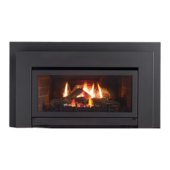
- Page 2 CONGRATULATIONS! You are the owner of a state-of-the-art Gas Insert by: FPI FIREPLACE PRODUCTS INTERNATIONAL LTD. ® The Regency Gas Fireplace Series has been designed to provide you with all the warmth and charm of a fi replace, at the fl ick of a switch. The models E21-NG3 and E21-LP3 of this series have been approved by Warnock Hersey for safety.
-
Page 3: Table Of Contents
TABLE OF CONTENTS OPERATING INSTRUCTIONS SAFETY LABEL Final Check..............27 Serial No. Decal ............4 Operating Instructions ..........27 Lighting Procedure ............27 REQUIREMENTS Shutdown Procedure ...........27 First Fire ..............27 MA Code - CO Detector ..........5 Copy of Lighting Plate Instructions ......28 Automatic Convection Fan Operation......29 INSTALLATION Normal Operating Sounds of Gas Appliances .....29 Important Message ............6... -
Page 4: Safety Label
SAFETY LABEL This is a copy of the label that accompanies each Regency ® Gas Insert. We have printed a copy of the contents here for your review. The safety label is located on the front inside base of the unit visible when the bottom louver is open. -
Page 5: Requirements
REQUIREMENTS MA Code - CO Detector (for the State of Massachusetts only) 5.08: Modifications to NFPA-54, Chapter 10 (2) Revise 10.8.3 by adding the following additional requirements: (a) For all side wall horizontally vented gas fueled equipment installed in every dwelling, building or structure used in whole or in part for residential purposes, including those owned or operated by the Commonwealth and where the side wall exhaust vent termination is less than seven (7) feet above finished grade in the area of the venting, including but not limited to decks and porches, the following requirements shall be satisfied:... -
Page 6: Installation
INSTALLATION IMPORTANT MESSAGE YOUNG CHILDREN SHOULD BE 9) Inspect the venting system annually for blockage and any signs of deterioration. CAREFULLY SUPERVISED WHEN SAVE THESE THEY ARE IN THE SAME ROOM INSTRUCTIONS 10) Any safety glass removed for servicing must AS THE APPLIANCE. -
Page 7: Policy For Solid Fuel Burning & Factory Built Fireplaces
INSTALLATION POLICY FOR SOLID INSTALLATION MINIMUM FIREPLACE FUEL BURNING & CHECKLIST CLEARANCES FACTORY BUILT 1) Locate your appliance. Refer to the "Clear- Diagram shows the minimum fi replace opening ances to Combustibles" and "Minimum required to be able to install the Regency ®... -
Page 8: Clearances To Combustibles
INSTALLATION CLEARANCES TO COMBUSTIBLES The minimum clearance from the side of the appliance to a combustible Note: A non-combustible mantel may be installed at a lower height side wall is 9 inches (229mm). The minimum clearance from the top of if the framing is made of metal studs covered with a non- the louver to a combustible mantel is 14 inches (356mm). -
Page 9: Gas Connection
INSTALLATION GAS CONNECTION For minimum and maximum supply pressure System Data see the System Data table. Only persons licensed to work with gas piping For altitude: Natural Gas 0-2000 ft. 1) If the appliance is to be installed into an may make the necessary gas connections to Propane: 0-4500 ft. -
Page 10: Wiring Diagrams
INSTALLATION WIRING DIAGRAMS Caution: Ensure that the wires do This heater does not require a 120V A.C. supply codes the current CSA C22.1 (in Canada) or for operation. In case of a power failure, the with the National Electrical Code ANSI/NFPA not touch any hot surfaces and are burner switch and the optional remote control/ 70-1987 (in USA). -
Page 11: Flue Connector Installation
INSTALLATION PROPANE Units and Units Equipped with DC Spark Boxes* *For installation of the DC Spark Box refer to the LP Conversion instructions in this manual. FLUE CONNECTOR INSTALLATION 1) Remove the screw holding the fl ue connector plate to the appliance. 2) Slide the plate out and attach to the fl... -
Page 12: Gas Pipe Pressure Testing
INSTALLATION COMBUSTION AND OFFSET FLUE to the vent by sheet metal screw or a B-Vent, single wall vent connector. VENTILATION AIR ADAPTOR B-Vent chimneys require a 1" clearance to combustibles. WARNING: This appliance needs fresh air A Offset Flue Adaptor Kit, Part #532-920 is A 3"... -
Page 13: Valve Description
INSTALLATION VALVE DESCRIPTION GAS INSERT a scrap piece of sheet metal (or other noncombustible material) in the upper louver, AERATION SYSTEM this will prevent the natural convection of the 1) Gas on/off knob unit from interfering with the test. 2) Manual high/low adjustment The aeration adjustment rod is attached to the Note: The smoke should be drawn into the air shutter which is located just above the orifi... -
Page 14: Log Set Installation
INSTALLATION LOG SET INSTALLATION 3) Fit log 27-23 into the pins on the back log tray. Read the instructions below carefully and refer to the images. Dangerous operating conditions may occur if the logs are not positioned in their correct locations. If the logs are broken do not use the unit until they are replaced. - Page 15 INSTALLATION 5) Rest the top of log 27-25 in the notch in log 27-24 and rest the bottom end of log 27-25 on the fi rebox base. 27-26 27-24 27-25 7) Fit the top end of log 27-27 into the pin in log 27-23 and rest the bottom end of log 27-27 against the 2nd grate post.
- Page 16 INSTALLATION 8) Fit log 27-28 into the pin on the left side of the burner. 27-29 27-28 10) Fit the top of log 27-30 into the pin on the right side of log 27-23 and rest the bottom of the log on the notches in logs 27-26 and 27-24. 27-30 27-23 9) Fit the left end of log 27-29 into the pin on the front left side of the...
- Page 17 INSTALLATION 11) Place embers along the front of the burner as shown. 12) Place rock wool along side the embers on the front of the burner as Ensure not to cover any burner ports. shown. Ensure not to cover any burner ports. 13) Separate platinum embers and place on the burner just in front of the logs.
-
Page 18: Faceplate & Trim Installation
INSTALLATION FACEPLATE & TRIM 4) Place the trim on the assembled faceplate 8) The power cord should be run behind the panels, aligning the wire connections from faceplate panel. INSTALLATION the switches with the notch on the left side panel. 9) Attach the brass trim to the faceplate by drilling a 1/8"... -
Page 19: Flush Glass
INSTALLATION FLUSH GLASS FLUSH LOUVERS 1) Install the bottom glass trim onto the glass 1) The Top Louver is held in place by Spring support. Clips. Push into place as shown. 2) Slide the glass into the bottom glass trim and secure with the glass clips using the 2 phillips head screws at the top. -
Page 20: Optional Bay Front
INSTALLATION OPTIONAL BAY FRONT BAY LOUVERS 1) Install top louver by sliding the two bracket IMPORTANT clips into the brackets located on top of the Flush glass must stay in place bay door. See below. The fi tted louver leaves when bay option is used. -
Page 21: Conversion Kit# 534-969 From Ng To Lp
INSTALLATION Conversion Kit# 534-969 from NG to LP THIS CONVERSION MUST BE DONE BY A QUALIFIED GAS FITTER IF IN DOUBT DO NOT DO THIS CONVERSION !! 10) Remove burner orifi ce with 1/2" Remove the Grate by removing the 2 Each Kit contains one LPG wrench. -
Page 22: Installation Of The Dc Sparker
INSTALLATION WARNING! 14) Check that the screw is clean and if 25) Remove the Piezo Ignitor by unscrewing necessary remove dirt. the nut at the back of the mounting Also check that the pilot and main bracket. burner injectors 15) Flip the screw (Fig. 3). are appropriate for the gas type. - Page 23 INSTALLATION 32) Connect the ground wire to the DC 35a) Remove the bottom louver (if in place) 29) Install the 1/2" bushing to the heat Sparker mounting bracket. by unscrewing the four screws located shield. on the hinges. 33) Install the supplied battery into the DC 30) Run the other end of the ground wire 35b) Location to mount the DC Sparker.
-
Page 24: Full Screen Doors
INSTALLATION FULL SCREEN DOORS 1) Hold the full screen door up against the unit in order to make the 3) Completely secure full screen door to the unit by securing 4 screws following wire connections. to the Left and Right Side Trim. Pull the ON/OFF connector wires thru the box and connect them to the switch. - Page 25 INSTALLATION 7) Install the Left and Right Side Screen Doors by placing over top of 5) Install Spring Hinges to the Left and Right Side of the bottom of the the hinges on the faceplate. fi rebox using 2 screws per hinge. Hold the door at a 45 degree angle to avoid scratching the faceplate.
-
Page 26: Remote Control
INSTALLATION REMOTE CONTROL WALL SWITCH WALL THERMOSTAT Use the Regency Remote Control Kit approved 1) Run the wire through the right or left side A wall thermostat may be installed if desired, for this unit. Use of other systems may void inlet opening. -
Page 27: Operating Instructions
OPERATING INSTRUCTIONS 7) Turn gas control knob counter clockwise to 6) Verify log placement. If the pilot cannot be FINAL CHECK "ON". seen when lighting the unit - the logs or the embers have been incorrectly positioned. Before leaving this unit with the customer, the 8) Use the rocker switch to operate main installer must ensure that the appliance is fi... -
Page 28: Copy Of Lighting Plate Instructions
OPERATING INSTRUCTIONS COPY OF LIGHTING PLATE INSTRUCTIONS LIGHTING INSTRUCTIONS Gas Inlet TO TURN OFF GAS APPLIANCE ® Regency E21-3 Gas Fireplace Insert... -
Page 29: Automatic Convection Fan Operation
MAINTENANCE MAINTENANCE AUTOMATIC WARNING: CHILDREN AND ADULTS INSTRUCTIONS SHOULD BE ALERTED TO THE CONVECTION FAN HAZARDS OF HIGH SURFACE OPERATION TEMPERATURE AND SHOULD 1) Always turn the gas valve to off before STAY AWAY TO AVOID BURNS OR cleaning. For relighting, refer to lighting CLOTHING IGNITION. -
Page 30: Removing Valve Assembly
MAINTENANCE 12) Remove the 2 screws on each side of the DOOR GLASS REMOVING VALVE fi rebox bottom and 4 screws on the rear REPLACEMENT ASSEMBLY wall., and lift out. Your Regency ® stove is supplied with high 1) Disconnect the power. temperature, 5 mm Neoceram ceramic glass that will withstand the highest heat that your unit will 2) Shut off the gas. -
Page 31: Parts List
PARTS LIST MAIN ASSEMBLY Part # Description Part # Description 530-518/P Fan Assembly Top Bay Louver Bottom Bay Louver 910-331/P Fan Motor (120V) 910-750 Power Cord (120V) 532-901 Brick Panel Set - Standard Brown 910-752 Wire Harness (Intermediate) 532-902 Brick Panel Set - Standard Red Firebox Bottom 532-903 Brick Panel Set - Herringbone Brown... -
Page 32: Burner Assembly & Log Set
PARTS LIST BURNER ASSEMBLY & LOG SET Part # Description 533-574/P Valve Assembly- NG 533-576/P Valve Assembly - LPG 910-468 Valve SIT - NG/LPG 910-190 Piezo Ignitor & Nut 910-076 Pilot Assembly - SIT - 3 fl ame -NG 910-077 Pilot Assembly - SIT - 3 fl... -
Page 33: Bay & Flush Front Assembly
PARTS LIST BAY & FLUSH FRONT ASSEMBLY Part # Description Part # Description Flush Door Bay Door 530-547/P Flush Door Assembly Complete 530-950 Complete Bay Front c/w Black Trim 107) 936-243 Gasket - Adhesive Backed 7/8" 106) 940-312/P Side Glass 153) Glass Side Trim 107) -
Page 34: Faceplate Assembly
PARTS LIST FACEPLATE ASSEMBLY Part # Description 910-330 Fan Speed Control (120 V) 904-569 Fan Speed Control Knob 910-246 Burner Switch ON/OFF (2 way) 400-950 Hearth Trim 1" Standard 320-940 Hearth Trim 1" Oversize 400-926 Hearth Trim 2" Standard 320-942 Hearth Trim 2"... -
Page 35: Warranty
WARRANTY Regency Fireplace Products are designed with reliability and simplicity in mind. In addition, our internal Quality Assurance Team carefully inspects each unit thoroughly before it leaves our facility. FPI Fireplace Products International Ltd. is pleased to extend this limited lifetime warranty to the original purchaser of a Excalibur Product. - Page 36 In addition, our internal Quality Assurance Team carefully inspects each unit thoroughly before it leaves our door. Regency Fireplace Products is pleased to extend this Limited Lifetime Warranty to the ® original purchaser of a Regency Product.
Need help?
Do you have a question about the E21 Gas Insert and is the answer not in the manual?
Questions and answers