Table of Contents
Advertisement
Quick Links
Energy
www.regency-fire.com
www.regency-fire.com
MODELS: E18E-NG11 Natural Gas E18E-LP11 Propane
Warning
FIre or explosion Hazard
failure to follow safety warnings exactly could result in serious
injury, death, or property damage.
- Do not store or use gasoline or other flammable vapors and liquids in the vicinity of this or any
other appliance.
- WHAT TO DO IF YOU SMELL GAS
•
Do not try to light any appliance.
• Do not touch any electrical switch: do not use any phone in your building.
Leave the building immediately.
• Immediately call your gas supplier from a neighbour's phone. Follow the gas supplier's
instructions.
• If you cannot reach your gas supplier, call the fire department.
- Installation and service must be performed by a qualified installer, service agency or the gas supplier.
Tested by:
Certified to/Certifié pour: CSA 2.17-2017
920-795
FPI FIREPLACE PRODUCTS INTERNATIONAL LTD. 6988 Venture St., Delta, BC Canada, V4G 1H4
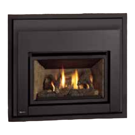
E18E Gas Insert
™
ANSI Z21.88-2019
CSA 2.33-2019
Installer: Please complete the details on the back cover and
leave this manual with the homeowner.
Homeowner: Please keep these instructions for future
reference.
E18E-11 Installation Manual
For Both The Montigo &
Firesong Gas Fireplaces only
08.12.24
Advertisement
Table of Contents

Related Manuals for Regency Fireplace Products Energy E18E


Summary of Contents for Regency Fireplace Products Energy E18E
- Page 1 E18E-11 Installation Manual Energy E18E Gas Insert For Both The Montigo & ™ Firesong Gas Fireplaces only www.regency-fire.com www.regency-fire.com MODELS: E18E-NG11 Natural Gas E18E-LP11 Propane Warning FIre or explosion Hazard failure to follow safety warnings exactly could result in serious injury, death, or property damage.
-
Page 2: Table Of Contents
TABLE OF CONTENTS Required Steps and Procedures for E18E Installation into the Following Montigo or Firesong Gas Fireplaces .......3 Separating the Outer Firebox Shell from Inner Firebox ..4 Modification of Montigo Econo Plus 28C ......5-13 Modification of Montigo EP28-2, EP28-3 or EP28-5 ..14-17 Modification of Montigo EP28-S2 ........ -
Page 3: Required Steps And Procedures For E18E Installation Into The Following Montigo Or Firesong Gas Fireplaces
E18E-11 REQUIRED STEPS AND PROCEDURES FOR E18E INSTALLATION INTO THE FOLLOWING MONTIGO OR FIRESONG GAS FIREPLACES IMPORTANT : All original vent systems must be inspected for carbon/soot build up prior to installation of the E18E. The installer should also ensure prior to installation that the existing vent system is adequate for the rated input of this appliance (21,600 BTU NG/20,500 BTU LP). -
Page 4: Separating The Outer Firebox Shell From Inner Firebox
E18E-11 SEPARATING THE OUTER FIREBOX SHELL FROM INNER FIREBOX 1. Lay fireplace insert on flat surface (use a drop sheet to protect surface). 2. Remove Glass Door by removing 2 x Phillips screws at the bottom of Glass Door Frame. 3. -
Page 5: Modification Of Montigo Econo Plus 28C
E18E-11 MODIFICATION OF MONTIGO ECONO PLUS 28C 1. Turn gas off to the unit, disconnect gas and power from unit. 2. Remove Top Louver Bars. 3. Remove Mesh Door Frame by removing 7 screws (See diagram below). Remove 7 screws - remove Mesh Door Frame (if installed). - Page 6 E18E-11 5. Remove Bracket and Thermodisc by removing 2 screws. Remove 2 screws - remove Thermodisc Bracket 6. Remove heat deflector by removing 3 bolts and nuts. Remove 3 bolts and nuts to remove heat deflector. 07.30.24 920-795...
- Page 7 E18E-11 7. Remove the rear baffle. Remove rear baffle 8. Remove 2 bolts from underneath, to remove valve, log tray, etc. Note: Disconnect any switch & thermopile wires off the valve so they don't snag when removing. Remove 2 bolts 07.30.24 920-795...
- Page 8 E18E-11 9. Lift entire assembly out. 10. Remove Serial No. Decal attached to valve assembly and affix to wall of 28C firebox. Montigo Serial Decal 07.30.24 920-795...
- Page 9 E18E-11 11. Flatten left and right louver brackets. Flatten louver brackets 12. Flatten flange (left ,right and rear) in locations shown below. Flatten flanges 07.30.24 920-795...
- Page 10 E18E-11 13. Cut to remove left and right cross piece at front of firebox. Also cut top front section at dotted lines as shown below. Note : it would be recommended to use eye and ear protection when using power tools. Top Front Section Cross piece Cut out front cross piece to remove...
- Page 11 E18E-11 Completed modification 15. Prior to installing faceplate - use a #30 drill bit to drill out the rivets and remove upper trim / heat shield from outer Montigo 28C faceplate. 16. Install new E18E outer faceplate to use as a template for measurements - ensure outer Faceplate is centered, mark and drill 2 holes per side.
- Page 12 E18E-11 Vent Connection and E18E Outer Shell Installation This install of the E18E uses Vent Connection Type A. Use part # 616-910 Flue Adaptor E18 (FS220N,EP28F,EP28-4/5/C). This kit includes an adaptor plate, adaptor plate gasket, 4" ID x 8 1/2" Long flex pipe,screws/washers. The Length of 4"...
- Page 13 E18E-11 1. Loosen 2 x Phillips screws on both right and left legs. See diagram 4. 2 screws Diagram 4 (right side shown) 28-F & 28F-2 Installation Speci cations 2. See diagram below for required leg setting. Montigo 28C Firebox E18E Outer Shell 8- 1/8"...
-
Page 14: Modification Of Montigo Ep28-2, Ep28-3 Or Ep28-5
E18E-11 MODIFICATION OF MONTIGO EP28-2, EP28-4 OR EP28-5 *Units could have any of the following Log Sets Installed: 2LB (2 Log Set), MB (2 Log Set), 4LB (4 Log Set) 1. Turn gas off to the unit, disconnect gas and power from unit. 2. - Page 15 E18E-11 8. Remove hood and inner baffle (See Diagram 5.3). Diagram 5.3 9. Bend down the three flanges at the bottom of the firebox or cut them off (See Diagram 5.4). Diagram 5.4 IMPORTANT: Modified edges must be flush to allow proper seating of the E18E outer shell.
- Page 16 E18E-11 Vent Connection and E18E Outer Shell Installation Vent Connection Type A This install of the E18E uses . Use part # 616-910 Flue Adaptor E18 (FS220N,EP28F,EP28-4/5/C). This kit includes an adaptor plate, adaptor plate gasket, 4" (102 mm) ID x 8 1/2" (216 mm) Long flex pipe,screws/washers. The length of 4"...
- Page 17 E18E-11 1. Loosen 2 x Phillips screws on both right and left legs. See diagram 4. 2 screws Diagram 4 (right side shown) 2. See diagram below for required leg setting. EP28 Installation Specifications Set legs (both Montigo EP 28-2/-4/-5 Firebox E18E Outer Shell EP28 Firebox right/left) to this...
-
Page 18: Modification Of Montigo Ep28-S2
E18E-11 MODIFICATION OF MONTIGO EP28-S2 *S2 comes with a 6 piece Log Set. 1. Turn gas off to the unit, disconnect gas and power from unit. 2. Remove Top and Bottom Louvers. 3. Remove Glass Door by removing 4 screws (See Diagram 6.1). Diagram 6.1 4. - Page 19 E18E-11 5. Remove Front Bar (See Diagram 6.3). Front Bar Diagram 6.3 6. Remove Primary and Secondary Limit Switches along with all wiring (See Diagram 6.4). Diagram 6.4 07.30.24 920-795...
- Page 20 E18E-11 7. Remove Insert (See Diagram 6.5). Diagram 6.5 8. Remove Efficiency Collar (See Diagram 6.6). Diagram 6.6 07.30.24 920-795...
- Page 21 E18E-11 9. Remove Fan (See Diagram 6.7). Diagram 6.7 10. Remove the leftover ends of the front bar on the Left and Right sides so that they are flush with the sides of the firebox. (See Diagram 6.8) Diagram 6.8 07.30.24 920-795...
- Page 22 E18E-11 11. Bend Down the Three Flanges at the Bottom of the Firebox or Cut them Off (see Diagram 6.9). Diagram 6.9 Edges must be flush to allow proper seating of the E18E outerbox. 07.30.24 920-795...
- Page 23 E18E-11 Vent Connection and E18E Outer Shell Installation Vent Connection Type A This install of the E18E uses . Use part # 616-910 Flue Adaptor E18 (FS220N,EP28F,EP28-4/5/C). This kit includes an adaptor plate, adaptor plate gasket, 4" (102 mm) ID x 8 1/2" (216 mm) Long flex pipe,screws/washers. The length of 4"...
- Page 24 E18E-11 1. Loosen 2 x Phillips screws on both right and left legs. See diagram 4. Diagram 4 (right side shown) 2. See diagram below for required leg setting. EP28 Installation Specifications Set legs (both Montigo EP 28-S2 Firebox E18E Outer Shell EP28 Firebox right/left) to this hole...
-
Page 25: Modification Of Montigo 28F Or 28F-2
E18E-11 MODIFICATION OF MONTIGO 28F OR 28F-2 1. Turn gas off to the unit, disconnect gas and power from unit. 2. Remove Top and Bottom Louvers. 3. Remove Screen Mesh (See Diagram 7.1) or Bifold Doors. Diagram 7.1 4. Remove Logs and Sand from Sand Pan. 5. - Page 26 E18E-11 6. Disconnect Pilot Gas Line and Pilot Thermopile from the Valve. Disconnect Thermostat wires from valve. Diagram 7.3 7. Disconnect Valve from the Main Burner Line (See Diagram 7.4). Note: You could also use a sawzall to cut the nipple and then remove the valve. Diagram 7.4 07.30.24 920-795...
- Page 27 E18E-11 8. Unscrew left and right side nuts using a wrench, under the firebox, holding down the Sand Pan. (see Diagram 7.5) Diagram 7.5 9. Remove Sand Pan and Pilot Assembly (see diagram 7.6). Note : it would be a good idea to remove the sand from the sand pan burner using a shop vacuum.
- Page 28 E18E-11 10. Cut out the Bottom of the Firebox (See Diagram 7.7). Cut must be clean - with Max. 1/4" of material left. Note : it would be recommended to use eye and ear protection. Diagram 7.7 11. Cut both sides of the Top Face (See Diagram 7.8). Diagram 7.8 07.30.24 920-795...
- Page 29 E18E-11 12. Bend Top Face Down (See Diagram 7.9). Diagram 7.9 13. Measure and draw a clear line 1" below the bottom of the exhaust collar. Draw the line the full width of the unit (See Diagram 7.10). Diagram 7.10 07.30.24 920-795...
- Page 30 E18E-11 14. Cut the Sides of the Top of the Firebox Flush with the Sides of the Firebox and Cut the Top of the Firebox 1” below the bottom of the Exhaust Collar (See Diagram 7.11 and 7.12). Diagram 7.11 Diagram 7.12 07.30.24 920-795...
- Page 31 E18E-11 14. Bend the Louver Mounts Flat. (See Diagram 7.13) Diagram 7.13 15. Final Firebox should look like Diagram 7.14. Diagram 7.14 Modified edges must be flush to allow proper seating of the E18E outerbox. 07.30.24 920-795...
- Page 32 E18E-11 Vent Connection and E18E Outer Shell Installation This install of the E18E uses Vent Connection Type A. Use part # 616-910 Flue Adaptor E18 (FS220N,EP28F/F2,EP28-4/5/C). This kit includes an adaptor plate, adaptor plate gasket, 4" ID x 8 1/2" Long flex pipe,screws/washers. The Length of 4"...
- Page 33 E18E-11 1. Loosen 2 x Phillips screws on both right and left legs. See diagram 4. 2 screws Diagram 4 (right side shown) 2. See diagram below for required leg setting. 28-F & 28F-2 Installation Specifications Set legs (both right/left) E18E Outer Shell Montigo 28F/28F-2 Firebox to this hole...
-
Page 34: Modification Of Montigo 28F-3
E18E-11 MODIFICATION OF MONTIGO 28F-3 1. Turn gas off to the unit, disconnect gas and power from unit. 2. Remove Top and Bottom Louvers. 3. Remove Screen Mesh (See Diagram 1) or Bifold Doors. Diagram 1 4. Remove Logs and Sand from Sand Pan (see diagram 2). Note : it would be a good idea to remove the sand from the sand pan burner using a shop vacuum. - Page 35 E18E-11 6. Disconnect valve from main burner Line (See Diagram 3). Note: You could also use a sawzall to cut the nipple and then remove the valve. Diagram 3 7. Unscrew left and right side nuts using a wrench, under the firebox, holding down the Sand Pan. (see Diagram 4) Diagram 4 07.30.24...
- Page 36 E18E-11 8. Remove sand pan and pilot assembly. Note: Shown with sand which would have been removed in step 4. Diagram 5 9. Cut the plate located at the bottom of the firebox, see diagram 6. Diagram 6 Cut here to remove bar 07.30.24 920-795...
- Page 37 E18E-11 10. Cut out the bottom of the Firebox (See Diagram 7) Cut must be clean - with Max. 1/4" of material left. Note: It would be recommended to use eye and ear protection. Diagram 7 Diagram 8 Cut here to remove 07.30.24 920-795...
- Page 38 E18E-11 11. Unscrew the top bar from location shown below. See diagram 9. Top Bar Diagram 9 07.30.24 920-795...
- Page 39 E18E-11 12. Unscrew the top plate located between the 2 fixed bars. See diagram 10. Top Plate Diagram 10 13. Unscrew the plate locating underneath. See diagram 11. Plate Diagram 11 07.30.24 920-795...
- Page 40 E18E-11 14. Unscrew the left & right side* and back plates located in the firebox. See diagrams 12 & 13. *Not all unit have side plates. Diagram 12 Diagram 13 07.30.24 920-795...
- Page 41 E18E-11 15. Remove the inside plate located at the rear of the cut plate. See diagram 14. Inside Plate Diagram 14 16. Cut the sides of the top face. See diagram 15. Note: It would be recommended to use eye and ear protection. Diagram 15 07.30.24 920-795...
- Page 42 E18E-11 17. Bend top face down (See Diagrams 16 & 17). Diagram 16 Diagram 17 07.30.24 920-795...
- Page 43 E18E-11 18. Measure and draw a straight line 1" below the bottom of the exhaust collar. Draw the line the full width of the unit. Cut the sides of the top of the firebox flush with the sides of the firebox and cut the top of the firebox 1” below the bottom of the exhaust collar.
- Page 44 E18E-11 20. Final modified firebox should look similar to Diagram 20 below. Note: Clean up any sharp edges. Diagram 20 07.30.24 920-795...
- Page 45 E18E-11 Vent Connection and E18E outer Shell Installation This install of the E18E uses Vent Connection Type A. Use part # 616-910 Flue Adaptor E18 (FS220N,EP28F/F2,EP28-4/5/C). This kit includes an adaptor plate, adaptor plate gasket, 4" ID x 8 1/2" Long flex pipe,screws/washers. The Length of 4"...
- Page 46 E18E-11 1. Loosen 2 x Phillips screws on both right and left legs. See diagram 4. 2 screws Diagram 4 (right side shown) 2. See diagram below for required leg setting. 28-F & 28F-2 Installation Specifications Set legs (both right/left) E18E Outer Shell Montigo 28F-3 Firebox 28-F / 28F-2 Firebox...
-
Page 47: Modification Of Montigo 36Sr
E18E-11 MODIFICATION OF MONTIGO 36SR *MUST USE FULL LENGTH 4" (102 MM) LINER A flue adaptor is not required for this installation as the 4" (102 mm) Liner will attach to the outer flue adaptor collar on the E18E. 1. Turn gas off to the unit, disconnect gas and power from unit. 2. - Page 48 E18E-11 6. Remove Air Inlet Strip (See Diagram 8.3). Diagram 8.3 7. Remove Brick Liner Panels (See Diagram 8.4). Diagram 8.4 07.30.24 920-795...
- Page 49 E18E-11 8. Unscrew and Remove Trim Around Sand Pan (See Diagram 8.5). Diagram 8.5 9. Disconnect pilot gas line and pilot thermopile from valve. Also disconnect any switch wires which may be connected to the gas valve. 10. Disconnect valve from main burner gas line. 11.
- Page 50 E18E-11 12. Unscrew left and right nuts using a wrench underneath the firebox holding down the sand pan. (See Diagram 8.7) 13. Remove Sand Pan and Pilot Assembly. Diagram 8.7 14. Unscrew the bottom of the firebox. (See Diagram 8.8) Diagram 8.8 07.30.24 920-795...
- Page 51 E18E-11 15. Unscrew the firebox top front flange, making sure to place the top left and right corner screws back in (See Diagram 8.9 and 8.10). Diagram 8.9 Diagram 8.10 07.30.24 920-795...
- Page 52 E18E-11 16. Remove Louver Supports in all 4 corners of the appliance (See Diagram 8.11). Diagram 8.11 17. Final firebox should look like diagram 8.12. Diagram 8.12 Modified edges must be flush to allow proper seating of the E18E outerbox. 07.30.24 920-795...
- Page 53 E18E-11 Vent Connection and E18E outer Shell Installation This install of the E18E uses a full length 4" liner. The length of 4" flex needed depends on the height of the B vent chimney. Slide the flex pipe all the way up to the top of the b vent chimney system. Also See Installation of E18E into Existing Units for General Installation Guidance in this manual for Vent Configurations &...
- Page 54 E18E-11 1. Loosen 2 x Phillips screws on both right and left legs. See diagram 4. 2 screws Diagram 4 (right side shown) 2. See diagram below for required leg setting. Montigo 36SR Installation Specifications Montigo 36SR Firebox 36SR Firebox Set legs (both E18E Outer Shell right/left) to this...
-
Page 55: Modification Of Firesong 220N
E18E-11 MODIFICATION OF FIRESONG 220N 1. Turn gas off to the unit, disconnect gas and power from unit. 2. Remove Valve Cover (See Diagram 9.1). Diagram 9.1 3. Remove the Bottom of the Firebox and Sand Pan in one assembly (See Diagram 9.2). Diagram 9.2 07.30.24 920-795... - Page 56 E18E-11 4. Unscrew and Remove Front Inner Baffle (See Diagram 9.3). Diagram 9.3 5. Cut the Sides of the Rear Inner Baffle at the Back of the Firebox (See Diagram 9.4). Diagram 9.4 6. Bend the Inner Rear Baffle up so it is flush with the back of the Firebox or cut off the Baffle if it will not bend flat with the back of the Firebox.
- Page 57 E18E-11 7. Cut The Top Front Flange of the Firebox (See Diagram 9.5). Note: It would be recommended to use eye and ear protection. Diagram 9.5 8. Cut off support tab at the top of the firebox and final firebox should look like Diagram 9.6. Diagram 9.6 Modified edges must be flush to allow proper seating of the E18E outerbox.
- Page 58 E18E-11 Vent Connection and E18E outer Shell Installation This install of the E18E uses Vent Connection Type A. Use part # 616-910 Flue Adaptor E18 (FS220N,EP28F,EP28-4/5/C). This kit includes an adaptor plate, adaptor plate gasket, 4" (102 mm)ID x 8 1/2" (216 mm) Long flex pipe,screws/washers. The Length of 4"...
- Page 59 E18E-11 1. Loosen 2 x Phillips screws on both right and left legs. See diagram 4. 2 screws Diagram 4 (right side shown) Firesong 220N Installation Specifications 2. See diagram below for required leg setting. 3. Install with supplied Phillips screws to prepunched holes and E18 Insert Outer Shell tighten previous screws that were loosened in Step 1.
-
Page 60: Modification Of Firesong 120N
E18E-11 MODIFICATION OF FIRESONG 120N 1. Turn gas off to the unit, disconnect gas and power (if fan is installed) from unit. 2. Remove Top Trim Pieces and Glass Doors- if installed (See Diagram 10.1). Diagram 10.1 3. Remove Lower Trim piece and Bottom Panel (See Diagram 10.2). Diagram 10.2 07.30.24 920-795... - Page 61 E18E-11 4. Remove Top Rail securing Mesh. (See Diagram 10.3). 5. Shut off and disconnect gas line from valve. Diagram 10.3 6. Unscrew and Remove Trim Around Sand Pan (See Diagram 10.4). Remove screw on right side to remove sand pan and base (Not shown). Trim around Sand Pan Diagram 10.4 07.30.24...
- Page 62 E18E-11 8. Remove logs (See Diagram 10.5). Diagram 10.5 9. Remove sand from the burner prior to lifting burner out. Note: It would be a good idea to remove the sand from the sand pan burner using a shop vacuum. Remove sand pan burner and valve by lifting up and out (Diagram 10.6).
- Page 63 E18E-11 10. Make 2 vertical cuts on Top Facing using a sawzal. (See Diagram 10.7). Note : it would be recommended to use eye and ear protection. Vertical Cuts Diagram 10.7 11. Remove Top Front Flange of Firesong firebox. (See Diagram 10.8). Remove tabs on right and left side of firebox.
- Page 64 E18E-11 12. Cut out mid section of Firesong firebox (See Diagram 10.9). Cut off bar at back of firebox. Back bar Diagram 10.9 13. Remove 6 screws, one at a time, and replace with pan head (wafer screws) - in locations shown below (Diagram 10.10). Diagram 10.10 07.30.24 920-795...
- Page 65 E18E-11 IMPORTANT: Cut out Firesong firebox and install support one side at a time. 14. Cut out right side of existing Firesong firebox (See Diagrams 10.11, 10.12 & 10.13). Left and right cutout begins on front face - see Diagram 10.12. Diagram 10.11 Diagram 10.12 07.30.24...
- Page 66 E18E-11 Diagram 10.13 15. Repeat steps on left side. 16. Install supplied support section with 8 screws to reinforce Firesong firebox. (See Diagram 10.14). Diagram 10.14 07.30.24 920-795...
- Page 67 E18E-11 17. Remove existing Firesong rating plate from cut out firebox. This rating plate must be retained and affixed to the unit (See Diagram 10.15 and 10.16). 18. Final modified firebox should look like Diagram 10.16 NOTE: Shown with flue collar and 6" length of flex installed. Diagram 10.15 Firesong decal affixed Diagram 10.16...
- Page 68 E18E-11 IMPORTANT NOTE: Separate inner and outer firebox on E18E (see instructions in this manual) Before installing outer firebox - lay on a flat surface and trim off 1-1/4" of each firebox fastening flange as shown below. 07.30.24 920-795...
- Page 69 E18E-11 Vent Connection and E18E outer Shell Installation This install of the E18E uses part # 616-911 Flue Adaptor E18 (Firesong 120N). This kit includes a 4" (102 mm)ID x 6" (152 mm) Long flex pipe, screws/washers. Remove top flue adaptor from unit by removing 1 Philips screw and slide backward. Adjust flue adaptor length by resetting screw from Set 4 to Set 8 - see Diagram below.
- Page 70 E18E-11 1. Loosen 2 x Phillips screws on both right and left legs. See diagram 4. 2 screws Diagram 4 (right side shown) 2. See diagram below for required leg setting. Firesong 220N Installation Specifications Firesong 120 Firebox E18 Insert Firesong 220N Firebox 6-1/8"...
-
Page 71: E18 Installation Into Existing Units
E18E-11 INSTALLATION OF THE E18E INTO EXISTING UNITS STEP #1: VENT CONNECTION TYPE A Adaptor Plate Gasket 1. Attach the Flex Vent Section to the Adaptor Plate using 3 self drilling sheet metal screws. 2. Using 4 Sheet Metal Screws, attach the Adaptor Plate, Vent Section and Adaptor Plate Gasket to the top of the existing Fire Box. - Page 72 E18E-11 STEP #2: OUTER SHELL INSTALLATION Vent Slide Plate Existing Firebox attachement screw Vent Slide Plate 1. Slide outer shell back into the existing firebox, ensure the vent slide plate is Step #2: properly engaged with the outer shell. Move the outer shell back until the left and right flanges contact the existing The E installed firebox.
- Page 73 E18E-11 STEP #4: SURROUND INSTALLATION SURROUND INSTALLATION Run wire harness from unit through notch in mounting bracket ONLY TRIM KIT SUPPLIED BY THE MANUFACTURER SHALL BE and then to control box as shown below. USED IN THE INSTALLATION OF THIS APPLIANCE. Remove glass door and screen from unit by removing 2 screws.
- Page 74 E18E-11 MONTIGO 28 F3 ONLY Attach front faceplate with 4 screws (2 on each mounting 12. To install fi ller piece, slide under faceplate and secure to bracket). (Touch up screws with black paint, after install.) backside of faceplate with magnets. Diagram 13.5 9.
- Page 75 E18E-11 RECYCLING PRODUCT LIFE CYCLE: By recycling your used appliances, you divert waste from your local landfills and help the environment. You also reduce the need for raw materials to manufacture new products. Contact your local municipality for appliance recycling services, local recycling programs, or appliance removal services to ensure your Regency appliance components, and packaging are properly recycled.
- Page 76 Installer: Please complete the following information Dealer Name & Address: _____________________________ _________________________________________________ Installer: _________________________________________ Phone #: _________________________________________ Date Installed: _____________________________________ Serial #: __________________________________________ Printed in Canada Regency and Energy are trademarks of FPI Fireplace Products International Ltd. © Copyright 2024, FPI Fireplace Products International Ltd. All rights reserved.
Need help?
Do you have a question about the Energy E18E and is the answer not in the manual?
Questions and answers