
Related Manuals for Moxa Technologies PowerTrans PT-7728-F-24


Summary of Contents for Moxa Technologies PowerTrans PT-7728-F-24
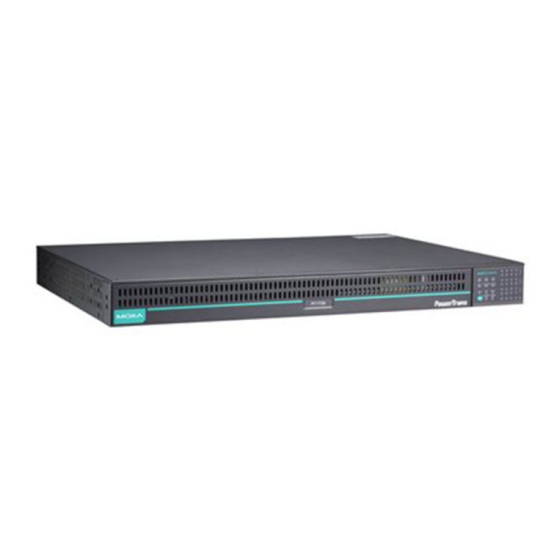
- Page 1 PT-7728/7828 Quick Installation Guide Moxa PowerTrans Switch Version 9.2, May 2021 Technical Support Contact Information www.moxa.com/support 2021 Moxa Inc. All rights reserved. P/N: 1802077280019 *1802077280019*...
-
Page 2: Package Checklist
Package Checklist The Moxa PowerTrans switch is shipped with the following items. If any of these items are missing or damaged, please contact your customer service representative for assistance. • 1 Moxa PowerTrans Switch • RJ45 to DB9 console port cable •... - Page 3 Dimensions (unit = mm) Fast Ethernet Interface Modules (slots 1, 2, and - 3 -...
-
Page 4: Rack Mounting
Gigabit Ethernet Interface Modules (for slot 4) Rack Mounting Use four screws to attach the PT switch to a standard rack. NOTE Two additional rack-mount ears can be ordered as an option. Use them to secure the rear of the chassis in high-vibration environments. -
Page 5: Wiring The Relay Contact
Wiring the Relay Contact Each PT switch has one relay output. Refer to the next section for detailed instructions on how to connect the wires to the terminal block connector, and how to attach the terminal block connector to the terminal block receptor. -
Page 6: Led Indicators
LED Indicators Color State Description System LEDs System has passed self-diagnosis test on boot-up and is ready to GREEN run. STAT System is undergoing the self- Blinking diagnosis test. System failed self-diagnosis on boot-up. Power is being supplied to the main module’s power input PWR1. -
Page 7: Specifications
Color State Description Mode LEDs The corresponding module port’s link is active. The corresponding module port’s LNK/ACT GREEN Blinking data is being transmitted. The corresponding module port’s link is inactive. The corresponding module port’s data is being transmitted at 10 Mbps. -
Page 8: Rack Mounting Instructions
Optical Fiber (100BaseFX) Distance Multi-mode: 0 to 5 km, 1300 nm (50/125μm, 800 MHz*km) 0 to 4 km, 1300 nm (62.5/125μm, 500 MHz*km) Single mode: 0 to 40 km, 1310 nm (9/125μm, 3.5 PS/(nm*km)) 0 to 80 km, 1550 nm (9/125um, 19 PS/(nm*km)) Min. -
Page 9: Restricted Access Locations
3. Mechanical Loading: Mounting of the equipment in the rack should be such that a hazardous condition is not achieved due to uneven mechanical loading. 4. Circuit Overloading: Consideration should be given to the connection of the equipment to the supply circuit and the effect that overloading of the circuits might have on overcurrent protection and supply wiring. - Page 10 Moxa’s address: 4 Fl., No. 135, Lane 235, Baoqiao Road, Xindian District, New Taipei City, 231 Taiwan - 10 -...
Need help?
Do you have a question about the PowerTrans PT-7728-F-24 and is the answer not in the manual?
Questions and answers