Moxa Technologies PowerTrans PT-7728 Hardware Installation Manual
Hide thumbs
Also See for PowerTrans PT-7728:
- User manual (120 pages) ,
- Quick installation manual (11 pages) ,
- Hardware installation manual (9 pages)

Related Manuals for Moxa Technologies PowerTrans PT-7728


Summary of Contents for Moxa Technologies PowerTrans PT-7728
- Page 1 PT-7728/7828 Hardware Installation Guide Moxa PowerTrans Switch Seventh Edition, January 2014 2014 Moxa Inc. All rights reserved. Reproduction without permission is prohibited. P/N: 1802077280015 www.ipc2u.ru www.moxa.pro...
-
Page 2: Package Checklist
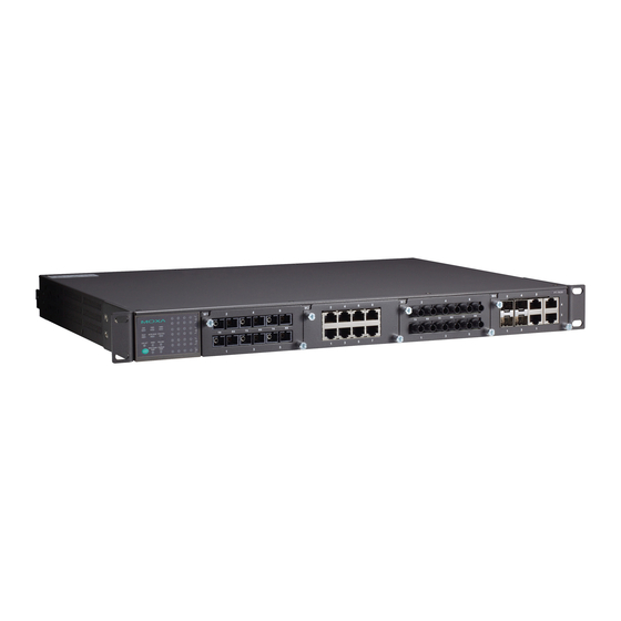
Package Checklist The Moxa PowerTrans switch is shipped with the following items. If any of these items are missing or damaged, please contact your customer service representative for assistance. • 1 Moxa PowerTrans Switch • Hardware Installation Guide • CD-ROM with User’s Manual and SNMP MIB file •... - Page 3 Dimensions (unit = mm) Fast Ethernet Interface Modules (slots 1, 2, and 3) - 3 - www.ipc2u.ru www.moxa.pro...
-
Page 4: Rack Mounting
Gigabit Ethernet Interface Modules (for slot 4) Rack Mounting Use four screws to attach the PT switch to a standard rack. NOTE Two additional rack-mount ears can be ordered as an option. Use them to secure the rear of the chassis in high-vibration environments. -
Page 5: Wiring The Relay Contact
Wiring the Relay Contact Each PT switch has one relay output. Refer to the next section for detailed instructions on how to connect the wires to the terminal block connector, and how to attach the terminal block connector to the terminal block receptor. -
Page 6: Led Indicators
LED Indicators System LEDs Color State Description System has passed self-diagnosis test on boot-up and is ready to run. GREEN System is undergoing the STAT Blinking self-diagnosis test. System failed self-diagnosis on boot-up. Power is being supplied to the main module’s power input PWR1. -
Page 7: Specifications
Mode LEDs Color State Description The corresponding module port’s link is active. The corresponding module port’s LNK/ACT GREEN Blinking data is being transmitted. The corresponding module port’s link is inactive. The corresponding module port’s data is being transmitted at 10 Mbps. - Page 8 Optical Fiber (100BaseFX) Distance Multi-mode 0 to 5 km, 1300 nm (50/125μm, 800 MHz*km) 0 to 4 km, 1300 nm (62.5/125μm, 500 MHz*km) Single-mode 0 to 40 km, 1310 nm (9/125μm, 3.5 PS/(nm*km)) 0 to 80 km, 1550 nm (9/125um, 19 PS/(nm*km)) Min.
Need help?
Do you have a question about the PowerTrans PT-7728 and is the answer not in the manual?
Questions and answers