Table of Contents
Advertisement
Quick Links
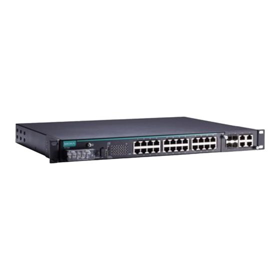
(24-Port Copper Models)
Quick Installation Guide
Moxa Americas:
Toll-free: 1-888-669-2872
Tel:
1-714-528-6777
Fax:
1-714-528-6778
Moxa Europe:
Tel:
+49-89-3 70 03 99-0
Fax:
+49-89-3 70 03 99-99
Moxa India:
Tel:
+91-80-4172-9088
Fax:
+91-80-4132-1045
PT-7528 Series
Moxa PowerTrans Switch
Edition 3.0, February 2017
Technical Support Contact Information
www.moxa.com/support
2017 Moxa Inc. All rights reserved.
Moxa China (Shanghai office):
Toll-free: 800-820-5036
Tel:
+86-21-5258-9955
Fax:
+86-21-5258-5505
Moxa Asia-Pacific:
Tel:
+886-2-8919-1230
Fax:
+886-2-8919-1231
P/N: 1802075280022
*1802075280022*
Advertisement
Table of Contents

Subscribe to Our Youtube Channel
Related Manuals for Moxa Technologies PT-7528-24TX-HV


Summary of Contents for Moxa Technologies PT-7528-24TX-HV
- Page 1 PT-7528 Series (24-Port Copper Models) Quick Installation Guide Moxa PowerTrans Switch Edition 3.0, February 2017 Technical Support Contact Information www.moxa.com/support Moxa Americas: Moxa China (Shanghai office): Toll-free: 1-888-669-2872 Toll-free: 800-820-5036 Tel: 1-714-528-6777 Tel: +86-21-5258-9955 Fax: 1-714-528-6778 Fax: +86-21-5258-5505 Moxa Europe: Moxa Asia-Pacific: Tel: +49-89-3 70 03 99-0...
-
Page 2: Package Checklist
Package Checklist The Moxa PowerTrans switch is shipped with the following items. If any of these items are missing or damaged, please contact your customer service representative for assistance. • 1 Moxa PowerTrans switch • USB cable (Type A male to Type B male) •... - Page 3 Dimensions; unit = mm (in) Fiber Ethernet Interface Modules - 3 -...
-
Page 4: Rack Mounting
Rack Mounting Use six screws to attach the PT switch to a standard rack. Rack Mounting Kit PT-7528 Side View NOTE Two additional rack-mount ears can be ordered as an option. Use them to secure the rear of the chassis in high-vibration environments. -
Page 5: Wiring The Relay Contact
Wiring the Relay Contact Each PT-7528 switch provides two types of relay output, at the user’s option. Refer below for detailed instructions on how to connect the wires to the terminal block connector, and how to attach the terminal block connector to the terminal block receptor. -
Page 6: Usb Console Connection
Gigabit Ethernet 1000BaseTX Cabling The IEEE 802.3ab Gigabit Ethernet standard defines 1000 Mbps Ethernet communications over distances of up to 100 meters using all 4 pairs in category 5 (or higher) balanced unshielded twisted-pair cabling. For wiring guidelines, system designers and integrators should refer to the Telecommunications Industry Association (TIA) TIA/EIA-568-A wiring standard that characterizes minimum cabling performance specifications required for proper Gigabit Ethernet operation. -
Page 7: The Reset Button
ABC-02-USB Installation Plug the ABC-02-USB into the USB storage port of the Moxa PT-7528 series. We suggest attaching the ABC-02-USB to a wall with an M4 screw. USB Storage Port (Type A Connector) Pinouts Description VCC (+5 V) D- (Data-) D+ (Data+) GND (Ground) The Reset Button... - Page 8 Color State Description One of the following situations exists: • The signal contact is open. • ABC Loading/Saving Failure. • The port has been disabled because the ingress multicast and broadcast packets FAULT exceed the ingress rate limit. • Incorrect loop connection in a single switch.
-
Page 9: Specifications
Color State Description FAULT + Rotate MSTR/HEAD Blinking ABC-02-USB is importing/exporting files. + CPLR/TAIL Sequentially STATE + FAULT + 2 blinks per sec: The switch is being Blinking MSTR/HEAD discovered/located by MXview. + CPLR/TAIL Port’s 100 Mbps link is active GREEN Blinking Data is transmitting at 100 Mbps... -
Page 10: Warranty
Alarm Contact One relay output with current carrying capacity of 3 A @ 30 VDC or 3 A @ 240 VAC Optical Fiber (100BaseFX) Distance Multi-mode: 0 to 5 km, 1300 nm (50/125μm, 800 MHz*km) 0 to 4 km, 1300 nm (62.5/125μm, 500 MHz*km) Single mode: 0 to 40 km, 1310 nm (9/125μm, 3.5 PS/(nm*km)) Min. -
Page 11: Restricted Access Locations
4. Circuit Overloading: Consideration should be given to the connection of the equipment to the supply circuit and the effect that overloading of the circuits might have on overcurrent protection and supply wiring. Appropriate consideration of equipment nameplate ratings should be used when addressing this concern. 5.
Need help?
Do you have a question about the PT-7528-24TX-HV and is the answer not in the manual?
Questions and answers