Moxa Technologies PT-7710 Series Hardware Installation Manual
Powertrans switch
Hide thumbs
Also See for PT-7710 Series:
- Manual (84 pages) ,
- Hardware installation manual (9 pages) ,
- Quick installation manual (9 pages)
Advertisement
Quick Links
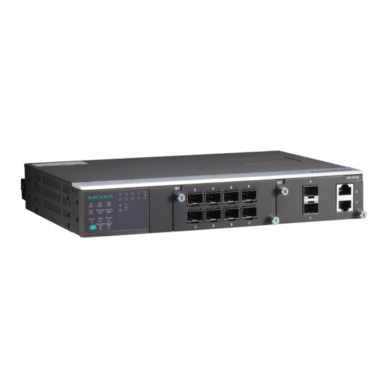
PowerTrans Switch
PT-7710 Series
Hardware Installation Guide
First Edition, May 2008
Package Checklist
The Moxa PowerTrans switch is shipped with the following items. If any
of these items are missing or damaged, please contact your customer
service representative for assistance.
1 Moxa PowerTrans Switch
Hardware Installation Guide
CD-ROM with User's Manual and SNMP MIB file
Moxa Product Warranty Statement
RJ45 to DB9 console port cable
Protective caps for unused ports
2 rack-mount ears
Panel Layouts
1
3
6
2
4
6
8
2
4
6
8
M1
1
3
5
7
STAT
PWR1
PWR2
2
M2
FAULT
MASTER
COUPLER
1
LNK/ACT
SPEED
FDX/HDX
COUPLER
RING PORT
PORT
MODE
1
3
5
7
4
2
Front View (Front Cabling)
PT-7710
Rear View (Front Cabling)
STAT
FAULT
LNK/ACT
MODE
RING PORT
Top View (Down Cabling)
1.
System status LEDs
2.
Interface Module mode LEDs
3.
Interface Module port LEDs
— 1 —
4.
Push-button switch to select mode for Interface Module
5.
Model Name
6.
Fast Ethernet Interface Modules
7.
Gigabit Ethernet Interface Modules
8.
Serial Console port
9.
10-pin terminal block for power inputs, and relay output
10. Rack Mounting Kit
Dimensions (unit = mm)
Side View
Fast Ethernet Interface Modules (for slot 1)
7
5 10
PT-7710
8
9
PM-7200-4MSC2TX/PM-7200-4SSC2TX
M1
PWR1
PWR2
M2
MASTER
COUPLER
SPEED
FDX/HDX
Gigabit/Fast Ethernet Interface Modules (for slot 2)
COMUPLER
PORT
PM-7200-2MSC/PM-7200-2SSC
P/N: 1802077100010
Rear View
266.5
Top View
462.5
Front View
96.8
96.8
PM-7200-8TX
PM-7200-1LSC6TX
96.8
96.8
96.8
PM-7200-6MSC/PM-7200-6SSC
PM-7200-2MSC4TX/PM-7200-2SSC4TX
96.8
96.8
96.8
PM-7200-4MST2TX
PM-7200-6MST
PM-7200-2MST4TX
86.6
86.6
86.6
PM-7200-2GTXSFP
PM-7200-1MSC/ PM-7200-1SSC
PM-7200-1MST
86.6
86.6
PM-7200-2MST
— 2 —
Rack Mounting
Use four screws to attach the PT switch to a
standard rack.
Wiring Requirements
WARNING
Be sure to disconnect the power cord before installing
and/or wiring your Moxa PowerTrans Switch.
Calculate the maximum possible current in each power
wire and common wire. Observe all electrical codes
dictating the maximum current allowable for each wire
size.
If the current goes above the maximum ratings, the wiring
could overheat, causing serious damage to your equipment.
Side View
Grounding the Moxa PowerTrans Switch
Grounding and wire routing help limit the effects of noise due to
electromagnetic interference (EMI). Run the ground connection from the
ground screw to the grounding surface prior to connecting devices.
Wiring the Power Inputs
The PT series of switches supports
dual redundant power supplies (DC
power only): VDC "Power Supply 1
(PWR1)" and "Power Supply 2
(PWR2)", or VAC "Power Supply
(PWR1)". The connections for
PWR1, PWR2 and the RELAY are
located on the terminal block. The
front view of the terminal block
connectors are shown below.
Wiring the Relay Contact
Each PT switch has one relay output. Refer to the next section for
detailed instructions on how to connect the wires to the terminal block
connector, and how to attach the terminal block connector to the terminal
block receptor.
FAULT: The relay contact of the 10-pin terminal block connector are
used to detect user-configured events. The two wires attached to the
RELAY contacts form an open circuit when a user-configured event is
triggered. If a user-configured event does not occur, the RELAY circuit
will be closed.
Safety First!
— 3 —
Advertisement

Related Manuals for Moxa Technologies PT-7710 Series


Summary of Contents for Moxa Technologies PT-7710 Series
- Page 1 Fast Ethernet Interface Modules standard rack. Gigabit Ethernet Interface Modules PowerTrans Switch Serial Console port 10-pin terminal block for power inputs, and relay output PT-7710 Series 10. Rack Mounting Kit Hardware Installation Guide Dimensions (unit = mm) Wiring Requirements First Edition, May 2008...
- Page 2 Console RS-232 (RJ45) When this PT switch disables the Wiring the Redundant Power Inputs coupling function. System LED STAT, PWR1, PWR2, FAULT, MASTER, Each PT switch has two sets of power inputs: power input 1 and power Indicators COUPLER Mode LEDs input 2.
Need help?
Do you have a question about the PT-7710 Series and is the answer not in the manual?
Questions and answers