Table of Contents
Advertisement
Quick Links
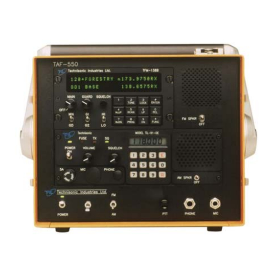
MODEL TAF-550
VHF/FM/AM MODULAR COMMUNICATIONS SYSTEM
THE MODEL TAF-550 INCLUDES THE FOLLOWING:
Model TFM-138B, FM Transceiver (138-174 MHz)
Model 91-DE, AM Transceiver (118-138 MHz)
Installation and
Operating Instructions
TiL Document No. 96RE187
Rev. D
JULY 2012
Technisonic Industries Limited
240 Traders Boulevard, Mississauga, Ontario L4Z 1W7
Tel: (905) 890-2113 Fax: (905) 890-5338
www.til.ca
Copyright by Technisonic Industries Limited. All rights reserved.
Advertisement
Table of Contents

Subscribe to Our Youtube Channel
Related Manuals for TIL TAF-550


Summary of Contents for TIL TAF-550
- Page 1 MODEL TAF-550 VHF/FM/AM MODULAR COMMUNICATIONS SYSTEM THE MODEL TAF-550 INCLUDES THE FOLLOWING: Model TFM-138B, FM Transceiver (138-174 MHz) Model 91-DE, AM Transceiver (118-138 MHz) Installation and Operating Instructions TiL Document No. 96RE187 Rev. D JULY 2012 Technisonic Industries Limited 240 Traders Boulevard, Mississauga, Ontario L4Z 1W7 Tel: (905) 890-2113 Fax: (905) 890-5338 www.til.ca...
- Page 3 REVISION HISTORY [ 96RE187 ] SECTION Edited DESCRIPTION DATE - PAGE - Original Document Global New Document Template (new file format) Title page changed, Headers/Footers added Added Revision page, Added Warranty page The 10 channel (memories) will no longer be available on all 91-DE based radios, ONLY 25.
- Page 4 iiii...
- Page 5 FCC ID label can not be seen, another label must be placed on the outside of the enclosure stating ‘contains FCC ID: IMA90-6R’. WARRANTY INFORMATION The TAF-550 Communications System is under warranty for one year from date of purchase. Failed units caused by defective parts, or workmanship should be returned to: Technisonic Industries Limited...
-
Page 7: Table Of Contents
INTRODUCTION ....................... 1-1 DESCRIPTION ........................1-1 1.2.1 FM Transceiver Model TFM-138B, P/N 921012-1, Opt. B ..........1-1 1.2.2 AM Transceiver Model Til-91-DE P/N 901006-1 ............... 1-3 1.2.3 Modular Case P/N 953209-1 ..................... 1-3 1.2.4 Microphone P/N 961069-1 ....................1-3 1.2.5 DC Power Cable for 12V Supply P/N 963213-1 ............... - Page 8 TFM-138B PC Download Cable - Wiring Diagram ..............3-24 LIST OF TABLES TABLE TITLE PAGE TAF-550 Modular Comm System - Data Sheet ............... 1-5 TFM-138B Transceiver 15-Pin D Connections ................ 2-3 Operators Switches, Controls and Indicators ................3-3 Channel/Function Selector Keypad ..................3-9 TAF-550 Installation & Operating Instructions...
-
Page 9: General Description
MS-DOS based computer with the provided software and optional PC download cable, P/N 943165-1. A DB-15 connector is provided on the rear panel of the TAF-550 chassis to facilitate the PC download function of the TFM-138B without the need to remove it from the TAF-550 chassis. - Page 10 TECHNISONIC INDUSTRIES LIMITED www.til.ca Figure 1.1 TAF-550 Comm System - General View (Open & Closed View) TAF-550 Installation & Operating Instructions TiL 96RE187 Rev D...
-
Page 11: Am Transceiver Model Til-91-De P/N 901006-1
TAF-550 front panel phone connector. The 91-DE Transceiver utilizes an internal speaker for this purpose. The lower front panel of the TAF-550 Modular Case provides a main power on/off switch, a transceiver backlighting on/off switch, a FM/AM transceiver selection switch, a PTT test button a 1/4"... -
Page 12: Modes Of Operation
MODES OF OPERATION The FM/AM selector switch located on the front panel of the TAF-550 is used to select operation of either the TFM-138B FM Transceiver or the 91-DE AM Transceiver. The receive audio of the selected transceiver will be routed over the headphone jack. Similarity the microphone connected to the TAF-550 front panel will route transmit audio to the selected transceiver. -
Page 13: Technical Summary
TECHNICAL SUMMARY A summary of electrical, operational, mechanical and physical characteristics of the transceivers, modular case and microphone indicated in Tables 1.1. TABLE 1.1 TAF-550 MODULAR COMM SYSTEM - DATA SHEET GENERAL: Power Requirements: AC Input Voltage/Current …………………………………………..….. 100 to 132 VAC @ 1.5 Amp DC Input Voltage/Current (24V configuration ……………….. - Page 14 TECHNISONIC INDUSTRIES LIMITED www.til.ca TABLE 1.1 TAF-550 MODULAR COMM SYSTEM - DATA SHEET (Continued) MODEL 91-DE, TRANSCEIVER TRANSMITTER: *Power Output (FCC) ..........…………………………...…… 10 Watts MAX *Power Output (ICAN) …………………………………………………………………… 8 Watts MAX Frequency Stability (-40EC to +55EC) …………………………………………..±0.00025% MAX Audio Input ……………………………………………………………………..
-
Page 15: Preparation For Use
1 inch through the front cut-out of the TAF-550 chassis. Remove the DC and UHF RF connectors located on the back of the 91-DE chassis. Slide the 91-DE chassis back through the TAF-550 front cut-out and lift up and out of the back of the TAF-550 chassis. -
Page 16: Taf-550 Modular Comm System - Disassembly
TECHNISONIC INDUSTRIES LIMITED www.til.ca Figure 2.1 TAF-550 Modular Comm System - Disassembly TAF-550 Installation & Operating Instructions TiL 96RE187 Rev D... -
Page 17: Tfm-138B Adjustments And Custom Configuration
2.2.1 TFM-138B Wiring Connections The TFM-138B Transceiver’s 15 Pin D connector is prewired for use in the TAF-550 chassis. The following table provides the input/output signal information for each pin of this connector. The pins numbers are stamped on the connector located on the back panel of the TFM-138B. -
Page 18: Transmitter Power Adjustments
(see Figure 3-4) to produce a 3.5 KHz deviation. Verify that the deviation is at least 3 KHz on the following frequencies: 138.000 MHz, 162.000 MHz and 174.000 MHz. TAF-550 Installation & Operating Instructions TiL 96RE187 Rev D... - Page 19 TECHNISONIC INDUSTRIES LIMITED www.til.ca Figure 2.2 Internal Enable/Disable Jumper and Transmit High/Low Power Adjust Locations TAF-550 Installation & Operating Instructions TiL 96RE187 Rev D...
-
Page 20: Transmitter Sidetone Level Adjustment
138.000 MHz, 162.000 MHz and 174.000 MHz. Re-adjust R30 or R76 as required, if the deviation exceeds ±5 kHz or ±2.5 kHz, respectively. Place top cover on transceiver chassis and secure all eight (8) screws. TAF-550 Installation & Operating Instructions TiL 96RE187 Rev D... -
Page 21: Microphone And Sidetone Level, Main And Guard Squelch Adjustment
TECHNISONIC INDUSTRIES LIMITED www.til.ca Figure 2.3 Microphone and Sidetone Level, Main and Guard Squelch Adjustment Access Holes TAF-550 Installation & Operating Instructions TiL 96RE187 Rev D... -
Page 22: Deviation Adjustment Potentiometer Location
TECHNISONIC INDUSTRIES LIMITED www.til.ca Notes: R30 is for 5.0 KHz (wideband) Deviation Adjustment R76 is for 2.5 KHz (narrowband) Deviation Adjustment FIGURE 2.4 Deviation Adjustment Potentiometer Location TAF-550 Installation & Operating Instructions TiL 96RE187 Rev D... -
Page 23: 91-De Custom Configuration
Position 15 flathead screws through cover holes into chassis threaded inserts. Tighten screws with fingers. Tighten screws securing Transceiver Cover to Chassis. 2.3.5 Transceiver Replacement Replace 91-DE Transceiver into the TAF-550 Modular case by reversing the steps outlined in paragraphs 2.1.1, 2.1.2 and 2.1.3. 2.3.6 Operational Check Turn 91-DE Transceiver Unit On (Refer to Section 3). -
Page 24: Fixed Channel Jumper Locations
TECHNISONIC INDUSTRIES LIMITED www.til.ca Figure 2.5 Fixed Channel Jumper Locations TAF-550 Installation & Operating Instructions TiL 96RE187 Rev D 2-10... -
Page 25: Operating Instructions
This section includes a functional description of each switch, control, indicator and connector located on the front and rear panels of the TAF-550 Modular Comm System, including the PRESS TO TALK switch located on the microphone. Specific Operating instructions for both the TFM-138B and TiL-91-DE Transceivers are also included. -
Page 26: Taf-550 Front And Rear Panel Layout
TECHNISONIC INDUSTRIES LIMITED www.til.ca Figure 3.2 TAF-550 Front and Rear Panel Layout TAF-550 Installation & Operating Instructions TiL 96RE187 Rev D... - Page 27 TFM-138B FM TRANSCEIVER - Switches, Controls and Indicators MAIN Rx A logarithmic potentiometer determines the Main Receiver audio level VOLUME AND applied to the internal TAF-550 speaker or headset when the transceiver is POWER ON/OFF operated in the receive mode. Also incorporates main power switch. GUARD RX...
- Page 28 Tx mode or when the SPEAKER/PHONE connector is in use. SPEAKER Toggle switch will enable the TiL-91-DE internal speaker to be turned ON or ON/OFF OFF. SWITCH...
- Page 29 TFM-138B to be turned ON or OFF. SWITCH *AC FUSE A 2 Amp fuse protects the TAF-550 Modular Case power supply from power supply internal short circuit or transceiver short circuit. *EXTERNAL 12 A 5 Amp fuse protects the 12 volt nominal power supply line.
-
Page 30: General Operating Instructions
If desired connect a headphone to the front panel PHONE connector on the TAF-550. Use the FM/AM selector switch on the front panel of the TAF-550 chassis to select the Transceiver for which the microphone transmit and headphone receive operations will be routed to. -
Page 31: Transmitter Operation
“TX” or “TT” on the alphanumeric display of the TFM-138B. Refer to paragraph 3.4 for 91-DE Front Panel Keypad Operation and additional Operating modes. Refer to paragraph 3.5 for completeTFM-138B operating instructions. TAF-550 Installation & Operating Instructions TiL 96RE187 Rev D... -
Page 32: Receiver Operation
Refer to paragraph 3.4 for Front Panel Keypad Operation and additional Operating modes. 3.3.4 Switching OFF To switch off the transceiver: Set the POWER ON/OFF on transceiver to switch to OFF. Verify that all indicator LED's on the front panel are OFF. TAF-550 Installation & Operating Instructions TiL 96RE187 Rev D... - Page 33 91-DE FRONT PANEL KEYPAD OPERATION Note: The TiL-91-DE transceiver was available in either 10 or 25 channel versions until July 2012. The 25 channel version can be identified by ‘25’ or ‘1283T’ on the option label on those units. All units manufactured after July 2012 are 25 channel only.
-
Page 34: Keypad "Beeps
Transmitter Time-out A 90 second time-out timer is provided to prevent accidental continuous transmission. Press to initiate 90 second Tx time-out protection. Press to disable 90 second Tx time-out protection. TAF-550 Installation & Operating Instructions TiL 96RE187 Rev D 3-10... -
Page 35: Selecting A Frequency
After keypad entry of a desired frequency, normal Tx/Rx operation can begin or the frequency can be stored as a channel as described in paragraph 3.4.5 (Storing a Frequency to a Channel). TAF-550 Installation & Operating Instructions TiL 96RE187 Rev D... -
Page 36: Storing A Frequency To A Channel
Channel 01 frequency 119.750 MHz stored in the previous example will be displayed. previous example will be displayed. Press Press Note: To recall the permanently stored emergency channel 121.500 MHz, press"E","0". TAF-550 Installation & Operating Instructions TiL 96RE187 Rev D 3-12... -
Page 37: Transmit Inhibit
Recall Channel 0 as described in para. 3.4.6 (Recalling a Stored Channel). 117.975 will be displayed. Recall Channel 2 138.000 will be displayed. Press 117.975 will be displayed. Press 138.000 will be displayed. TAF-550 Installation & Operating Instructions TiL 96RE187 Rev D 3-13... -
Page 38: Search Mode
Pressing PTT once exits SCAN mode. Pressing PTT twice is required to Key the Transmitter. Press to enter SCAN mode. Press PTT to Lock on SCANned Frequency or Press to exit SCAN. TAF-550 Installation & Operating Instructions TiL 96RE187 Rev D 3-14... -
Page 39: Tfm-138B Operating Features
Only TX CTCSS tones or TX DPL codes may be programmed for the guard receiver. At the beginning of each line, an LED indicates open squelch. TAF-550 Installation & Operating Instructions TiL 96RE187 Rev D 3-15... -
Page 40: Operator's Switches And Controls - Tfm-138B
TECHNISONIC INDUSTRIES LIMITED www.til.ca FIGURE 3.3 Operator's Switches and Controls - TFM-138B TAF-550 Installation & Operating Instructions TiL 96RE187 Rev D 3-16... -
Page 41: Programming Instructions
Use the M.UP and M.DN keys to toggle between these functions (for details see paragraph 3.5.4). Once the desired condition has been selected, press ENTER. The display will show a "+" beside the memory channel number if scan is enabled. TAF-550 Installation & Operating Instructions TiL 96RE187 Rev D 3-17... -
Page 42: Scanning Function
During communications the five second timer is reset from the last Rx or Tx signal experienced. The radio resumes scanning once the Rx or Tx activity has ceased for more than five seconds. The SCAN key must be pressed to exit the scan mode. TAF-550 Installation & Operating Instructions TiL 96RE187 Rev D 3-18... -
Page 43: Direct Frequency Entry Mode
(except keyboard unlock) in the receive mode. The DTMF function during transmit will not be affected. To unlock the keyboard, press and hold the LOCK key for two seconds until the display indicates "UNLOCK". TAF-550 Installation & Operating Instructions TiL 96RE187 Rev D 3-19... -
Page 44: Variable Frequency Mode Function
Hz. Use the M.UP and M.DN keys to select the tone number you require. The following is a list of the available CTCSS tones: TAF-550 Installation & Operating Instructions TiL 96RE187 Rev D 3-20... - Page 45 A list of all usable and unique octal 3-digit DPL/DCS codes follows: 017* 266* 053* 122* 274* 356* 246* 446* 452* 523* (This list is continued on the next page) TAF-550 Installation & Operating Instructions TiL 96RE187 Rev D 3-21...
-
Page 46: Pc Memory/Programming Download Capability
Turn on the power supply and the TFM-138B first and then turn on the PC. Change to the \PCDLB directory and type: PCDLB and <enter>. The main menu will be displayed. TAF-550 Installation & Operating Instructions TiL 96RE187 Rev D 3-22... - Page 47 'DATA1' file. To have multiple databases, you can copy the data file to a new name and edit the 'DATA1' file again. To retrieve a database, copy it back to 'DATA1'. TAF-550 Installation & Operating Instructions TiL 96RE187 Rev D 3-23...
- Page 48 TECHNISONIC INDUSTRIES LIMITED www.til.ca FIGURE 3.4 TFM-138B Transceiver PC Download Cable - wiring diagram TAF-550 Installation & Operating Instructions TiL 96RE187 Rev D 3-24...
-
Page 49: Warranty
Technisonic. This Warranty shall not be transferable or assignable to any other persons, firms or corporations. For warranty registration please complete the on-line Warranty Registration Form found at www.til.ca.
Need help?
Do you have a question about the TAF-550 and is the answer not in the manual?
Questions and answers