Table of Contents
Advertisement
Quick Links
TDFM-7300-2
MULTIBAND P25 AIRBORNE TRANSCEIVER
Installation and
Operating Instructions
TiL Document No. 10RE430
Rev. A
NOVEMBER 2010
Technisonic Industries Limited
240 Traders Boulevard, Mississauga, Ontario L4Z 1W7
Tel: (905) 890-2113 Fax: (905) 890-5338
www.til.ca
Copyright 2009 by Technisonic Industries Limited. All rights reserved.
Advertisement
Table of Contents

Subscribe to Our Youtube Channel
Related Manuals for TIL TDFM-7300-2


Summary of Contents for TIL TDFM-7300-2
- Page 1 TDFM-7300-2 MULTIBAND P25 AIRBORNE TRANSCEIVER Installation and Operating Instructions TiL Document No. 10RE430 Rev. A NOVEMBER 2010 Technisonic Industries Limited 240 Traders Boulevard, Mississauga, Ontario L4Z 1W7 Tel: (905) 890-2113 Fax: (905) 890-5338 www.til.ca Copyright 2009 by Technisonic Industries Limited. All rights reserved.
- Page 3 REVISION HISTORY [ 10RE430 ] SECTION DESCRIPTION DATE Edited by - PAGE - Changed 70cm to 80cm. 26 Nov 2010...
- Page 5 Changes or modifications not expressly approved by Technisonic Industries could void the user’s authority to operate the equipment. WARRANTY INFORMATION The Model TDFM-7300-2 Transceiver is under warranty for one year from date of purchase. Failed units caused by defective parts, or workmanship should be returned to: Technisonic Industries Limited...
- Page 6 Canada. Only authorized factory dealers/installers are permitted to download and make use of these documents on behalf of their customers (end users) in support of regulatory agency approval. Please refer to the Technisonic web site www.til.ca for the latest issue of available STCs and letter of authorization for use.
-
Page 7: Table Of Contents
LH DATA, SB9600 BUSY, OPTB+, CTS OUT, BOOT DIN, RTSBIN and RS232DIN ..... 3-5 3.16 PANEL BACKLIGHTING ......................3-5 3.17 ANTENNA TUNER CONTROL LINES ..................3-5 3.18 POWER JUMPER ........................3-5 3.19 POST INSTALLATION EMI TEST ................... 3-9 WARRANTY ............................TDFM-7300-2 Installation & Operating Instructions TiL 10RE430A... - Page 8 TDFM 7300-2 Analog Band CTCSS/PL Codes ............... 2-14 Wire connections on a 25-Pin FEMALE D-Connector ............. 3-3 Wire connections on a 9-Pin FEMALE D-Connector ............... 3-3 Wire connections on a 15-Pin [high-density] FEMALE D-Connector ........3-4 TDFM-7300-2 Installation & Operating Instructions TiL 10RE430A...
-
Page 9: General Description
AES and/or DES-OFB encryption with OTAR in any of the available modules. Bands 1 through 4 on the TDFM-7300-2 are not normally frequency agile. In order to have the ability to change the frequencies at the front panel, the FPP (front panel programming) option must be ordered. - Page 10 TECHNISONIC INDUSTRIES LIMITED www.til.ca The following part numbers represent typical TDFM-7300-2 model variations: 3-band TDFM-7300-2 Variations P/N 061245-1-73U188 One VHF and two 800 MHz, type I modules with Green display. P/N 061245-3-73U148 One VHF, UHF low and 800/700, type II modules with Green display.
- Page 11 TECHNISONIC INDUSTRIES LIMITED www.til.ca TDFM-7300-2 Model Variations with type II Modules (-3,-4) 4-Band TDFM-7300-2 Model Variations TDFM-7300-2, P/N 061245-3-73YXXX/P73ZZZ GREEN display. TDFM-7300-2, P/N 061245-4-73YXXX/P73ZZZ RED display. TDFM-7300-2NV, P/N 061245-3-73YXXXNV/P73ZZZ GREEN NV display. 5-Band TDFM-7300-2 Model Variations (-73YXXXX) TDFM-7300-2, P/N 061245-3-7YXXXX/P73ZZZ GREEN display.
-
Page 12: Technical Characteristics
*Digital 1% BER (12.5kHz) 0.35 0.35 0.45 *Digital 5% BER (12.5kHz) 0.25 0.25 0.25 **Analog with 12dB SINAD 0.25 0.25 0.25 Selectivity in dB: 25 kHz Channel 12.5 kHz Channel Intermodulation (dB) * ** TDFM-7300-2 Installation & Operating Instructions TiL 10RE430A... - Page 13 25 kHz Channel 12.5 kHz Channel Intermodulation * ** *Measured in digital mode per TIA / EIA IS 102.CAAA under nominal conditions. ** Measured in analog mode per TIA / EIA 603 under nominal conditions. TDFM-7300-2 Installation & Operating Instructions TiL 10RE430A...
- Page 14 Third Order Intermodulation -70 dB Image Attenuation -60 dB FM Acceptance ± 6 kHz Hum and Noise Better than 40 dB Audio Distortion less than 5% Antenna Conducted Emission less than -70 dBm TDFM-7300-2 Installation & Operating Instructions TiL 10RE430A...
- Page 15 ± 2.5 ppm Harmonic Attenuation -60 dB below carrier level FM Hum And Noise -35 dB Audio Input 50 mV at 2.5 kHz into input circuit for ±3.5kHz deviation, adjust. Audio Distortion Less than 5% TDFM-7300-2 Installation & Operating Instructions TiL 10RE430A...
- Page 16 TECHNISONIC INDUSTRIES LIMITED www.til.ca Page left intentionally blank TDFM-7300-2 Installation & Operating Instructions TiL 10RE430A...
-
Page 17: Operating Instructions
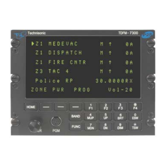
It is possible to connect the transceiver such that both methods are used. FRONT PANEL Refer to the diagrams below: FIGURE 2-1 Front Panel Controls – TDFM-7300-2 Transceiver TDFM-7300-2 Installation & Operating Instructions TiL 10RE430A... -
Page 18: Power Switch
For example, programming a soft key to CHAN would be redundant since there is already a channel function using the knobs. Using the CHAN soft key would also not update the channel number on the display, causing some confusion. TDFM-7300-2 Installation & Operating Instructions TiL 10RE430A... -
Page 19: Band Key
F1 – Top-side-button (purple button) on the portable. F2 – Centre-side-button (with one dot) on the portable. F3 – Bottom-side button (with two dots) on the portable. F4 - Top button (orange button) on the portable. TDFM-7300-2 Installation & Operating Instructions TiL 10RE430A... - Page 20 TECHNISONIC INDUSTRIES LIMITED www.til.ca TDFM-7300-2 Transceiver Recommended Keypad Menu Defaults: TDFM-7300 Conventional SmartNet / SmartZone Series Portable Operation Operation Transceiver ITEM ITEM Upper Side F1 Key Monitor Unprogrammed Button 1 Middle Side F2 Key Nuisance Delete Unprogrammed Button 2 Bottom Side...
-
Page 21: Mup(4) And Mdn(7) Keys (Memory Up And Down Keys)
TECHNISONIC INDUSTRIES LIMITED www.til.ca Bands 1 through 4 of the TDFM-7300-2 Transceiver are programmable by Motorola CPS™. The following settings may be programmed for each Conventional Channel in a module: Tx Frequency Zone Tx PL/DPL Code Channel Rx Frequency Name... -
Page 22: Esw(0) Key (Ergo Switch Key)
Switch on the transceiver as described in 2.3. Select the desired band by pressing the BAND key. Select the TDFM-7300-2 on the aircraft audio panel. Press the knob again so that CHAN shows up on the bottom right of the display. Rotate the knob until the desired channel or talk group is selected. -
Page 23: Customer Programming Software (Cps)
2.16 CUSTOMER PROGRAMMING SOFTWARE (CPS™) Programming the Bands 1 – 4 of the TDFM-7300-2 is usually done with the use of third party programming software. Customer programming software or “CPS” must be supplied by Motorola. To make any changes to the programming in the Type II radio, Motorola CPS™ software must be used. -
Page 24: Pc 7000(Ii) Programming Cable For Type Ii Radios P/N 047365-1
TECHNISONIC INDUSTRIES LIMITED www.til.ca FIGURE 2.2: PC 7000(II) Programming cable for TYPE II radios P/N 047365-1 FIGURE 2.3: Encryption Keyload cable for TYPE II radios P/N 037348-1 TDFM-7300-2 Installation & Operating Instructions TiL 10RE430A... -
Page 25: Pc 6000(Ii) Programming Cable For Type Ii Radios P/N 047366-1
Programming Using Computers With No Serial Ports Newer PCs and laptops are now being made without serial ports. For those computers to program the TDFM-7300-2, a USB to serial adaptor will be required. USB to serial adaptors can be found at most computer stores. -
Page 26: Configuration Menu
2.17 CONFIGURATION MENU: Some features of the TDFM-7300-2 transceiver can be configured to the user’s preference. To enter the configuration menu, turn the unit on while simultaneously pressing the F4, ESW and TSW keys. Hold the keys until the display reads ‘Configuration Menu’. The following menu items can be changed or modified. -
Page 27: Keyloading Mode
2.18 KEYLOADING MODE If the TDFM-7300-2 is equipped with hardware encryption, then the Encryption keys will need to be loaded using a Motorola KVL 3000+® Keyloader. Keyloading must be done by putting the transceiver into flash upgrade mode by turning on the radio while holding the HOME key. -
Page 28: Front Panel Programming (Fpp) Mode (Bands 1 - 4)
Use the UP and DN keys to scroll to the desired letter and press the NXT CHANNEL NAME soft key to get to the next character. Press ‘OK’ when done. There will be a delay while the channel is saved, then the display will return to normal. TDFM-7300-2 Installation & Operating Instructions TiL 10RE430A 2-12... - Page 29 TECHNISONIC INDUSTRIES LIMITED www.til.ca The following is a list of TDFM-7300-2 CTCSS/PL/MOT CODES FOR BANDS 1 - 4: PL(Hz) MCODE PL(Hz) MCODE PL(Hz) MCODE PL(Hz) MCODE 67.0 97.4 141.3 206.5 69.3 100.0 146.2 210.7 71.9 103.5 151.4 218.1 74.4 107.2 156.7...
-
Page 30: Flash Upgrade Mode
Follow the instruction supplied with the flash upgrade kit for configuring and using the CPS. When flash upgrade is completed, press the EXIT soft key to reboot the 7300 to normal operation. For detailed instructions refer to TIL document 106517 “FLASH UPGRADE PROCEDURE FOR TDFM 6000/7000/7300 SERIES RADIOS”. -
Page 31: Vhf Low Band (Band 5) Operation - Analog Module Variances
PC Uploading and Downloading channels to band 5 is accomplished using Technisonic’s MultiTDP software which is supplied on a CD with the TDFM-7300-2 and from the TIL web site. (www.til.ca) The files are compatible with those used on our TFM-550 model. - Page 32 TECHNISONIC INDUSTRIES LIMITED www.til.ca This page left intentionally blank. TDFM-7300-2 Installation & Operating Instructions TiL 10RE430A 2-16...
-
Page 33: Installation Instructions
TRANSCEIVER INSTALLATION The TDFM-7300-2 Transceiver is designed to be Dzus mounted and should be installed in conjunction with an IN-7300 installation kit. See Figure 3-1 for an outline drawing of the unit with dimensions to facilitate the installation. -
Page 34: Outline Drawing
TECHNISONIC INDUSTRIES LIMITED www.til.ca FIGURE 3-1 Outline Drawing for Model TDFM-7300-2 TDFM-7300-2 Installation & Operating Instructions TiL 10RE430A... -
Page 35: Pin Locations And Connections
J2 Connections (9 Pin FEMALE D Connector) Pin # Description Ground Audio Combined PTT 4 PTT Combined Audio 4 Mic 4 Mic Combined On Power Speaker Combined TABLE 3-2 Wire connections on a 9 Pin FEMALE D Connector TDFM-7300-2 Installation & Operating Instructions TiL 10RE430A... -
Page 36: Installation (Wiring Instructions)
PTT5 Mic 5 TABLE 3-3 Wire connections on a 15 Pin [high-density] FEMALE D Connector INSTALLATION (WIRING INSTRUCTIONS) Figure 3-2 shows all required connections and recommended wire sizes for the TDFM-7300-2 transceiver. J1 (PINS 1 AND 14) MAIN GROUND: Both pins should be connected to ground. The main ground is internally connected to the chassis. -
Page 37: Ptt 1, 2, 3, 4, 5 And Combined
Connect according to the manufacturer’s instructions. In the case of the FLX-3050B, the tune indicator which is normally connected to a light, can be connected to pin 10 so that the tuning indication will show on the TDFM-7300-2 display. If a passive antenna is used, these lines shall remain unconnected. - Page 38 TECHNISONIC INDUSTRIES LIMITED www.til.ca FIGURE 3-2a Wiring connections for the TDFM-7300-2 Transceiver TDFM-7300-2 Installation & Operating Instructions TiL 10RE430A...
- Page 39 TECHNISONIC INDUSTRIES LIMITED www.til.ca FIGURE 3-2b Wiring connections notes for the TDFM-7300-2 Transceiver TDFM-7300-2 Installation & Operating Instructions TiL 10RE430A...
- Page 40 TECHNISONIC INDUSTRIES LIMITED www.til.ca This page left intentionally blank. TDFM-7300-2 Installation & Operating Instructions TiL 10RE430A...
-
Page 41: Post Installation Emi Test
3.19 POST INSTALLATION EMI TEST PURPOSE The purpose of this test is to identify any interference that the TDFM-7300-2 transceiver may cause with existing aircraft systems. TEST CONDITIONS The TDFM-7300-2 transceiver should be installed and function tested. The antenna VSWR should be checked. - Page 42 For example it is permissible for a VFR certified GPS to lose navigation capability while the TDFM-7300-2 unit is transmitting, providing that it recovers properly and promptly, but it is not permissible for an IFR Approach certified GPS to be affected in the same way.
- Page 43 Determine if the image frequency for the VHF Comm falls within the range of the TDFM-7300-2. If so, select a set of frequencies that will cause the TDFM-7300-2 to be set as close as possible to the image frequency. Any one of the many possible sets will suffice. Record those values in the spaces provided in the following chart.
- Page 44 Determine if the image frequency for the VOR/ILS Nav falls within the range of the TDFM-7300. If so, select two sets of frequencies that will cause the TDFM-7300-2 to be set as close as possible to the image frequency. Choose one set in the localizer frequency range and one in the VOR frequency range.
- Page 45 ILS to be used. Divide the glide slope frequency by 2 and program into the TDFM-7300-2. Fly the aircraft to intercept the localizer and glide slope (both needles centered) at 26 nm from the runway.
- Page 46 334.7 (108.1) 167.35 334.7 (108.1) 33.47 NOTES: Operate the TDFM-7300-2 transmitter on the following frequency for at least 20 seconds. Observe the Transponder for any spurious replies or loss of reply to test set. FREQUENCIES TRANSPONDER #1 TRANSPONDER #2 TDFM-7300-2...
- Page 47 TECHNISONIC INDUSTRIES LIMITED www.til.ca Modulate the TDFM-7300-2 transmitter on the following frequencies for at least 20 seconds. Observe the DME displays. Look for loss of distance information on the display. FREQUENCIES RESULTS DME 1 TDFM-7300-2 PASS FAIL 978 (108.0) 1020 (112.1)
- Page 48 Perform a coupled ILS approach to the aircraft's certified limits. Modulate the TDFM-7300- 2transmitter on the above frequencies for at least 20 seconds. Observe any effect on the autopilot. Repeat for second flight director/autopilot if equipped. Observations: TDFM-7300-2 Installation & Operating Instructions TiL 10RE430A 3-16...
- Page 49 (VHF, UHF Lo, and 800 MHz) ADF 1 & 2 Glideslope 1&2 (UHF Lo, UHF Hi, and 800 MHz) VOR/LOC 1&2 (UHF Lo, UHF Hi, and 800 MHz) Compass Directional Gyro Fuel Pressure Oil Temp TDFM-7300-2 Installation & Operating Instructions TiL 10RE430A 3-17...
- Page 50 TECHNISONIC INDUSTRIES LIMITED www.til.ca Amps Bus Voltage Fuel % Torque % Annunciators Digital Clock Oil Pressure DME 1&2 (VHF, UHF Lo, and 800 MHz) GPS 1&2 (UHF Lo and 800 MHz) TDFM-7300-2 Installation & Operating Instructions TiL 10RE430A 3-18...
- Page 51 TECHNISONIC INDUSTRIES LIMITED www.til.ca STEP SYSTEM PASS FAIL NOTES NOTES: TDFM-7300-2 Installation & Operating Instructions TiL 10RE430A 3-19...
- Page 52 Technisonic. This Warranty shall not be transferable or assignable to any other persons, firms or corporations. For warranty registration please complete the on-line Warranty Registration Form found at www.til.ca.
Need help?
Do you have a question about the TDFM-7300-2 and is the answer not in the manual?
Questions and answers