Table of Contents
Advertisement
Quick Links
Advertisement
Table of Contents

Subscribe to Our Youtube Channel
Related Manuals for TIL TiL-91-DE


Summary of Contents for TIL TiL-91-DE
-
Page 1: Operating Instructions
VHF/AM MOBILE TRANSCEIVER MODEL TiL-91-DE 7 WATT MOBILE SYSTEM NO 910200 (TMS-150) Installation and Operating Instructions Til Document No. 94RE146 Rev. A October 2001 Technisonic Industries Limited 240 Traders Blvd., Mississauga, Ontario L4Z 1P4 Tel:(905)890-2113 Fax:(905)890-5338 www.til.ca... - Page 2 WARRANTY INFORMATION The Base Stations, Model 91-DE series and Model Til 90-6R series are under warranty for one year from date of purchase. Failed units caused by defective parts, or workmanship should be returned to: Technisonic Industries Limited 240 Traders Blvd.
-
Page 3: Table Of Contents
TABLE OF CONTENTS Section Title Page GENERAL DESCRIPTION Introduction 1.1.1 Purpose of the System 1.1.2 Modes of Operation Technical Summary INSTALLATION INFORMATION Introduction Transceiver Location Vehicle Power Supply Power Input Cable Assembly Antenna Assembly 2.5.1 Antenna Location 2.5.2 Antenna Installation Mounting Bracket Installation Transceiver Installation Microphone Installation... - Page 4 LIST OF TABLES Table No. Title Page Leading Particulars Operator's Switches, Controls and Indicators Channel/Function Selector Keypad LIST OF ILLUSTRATIONS Figure No. Title Page Transceiver - General View Transceiver with Mounting Bracket - General View Power Input Cable Assembly - General View Microphone Assembly - General View Antenna Assembly - General View Transceiver Front Panel Layout...
-
Page 5: General Description
SECTION 1 GENERAL DESCRIPTION INTRODUCTION VHF/AM Mobile Transceiver System 910200 (Item No. TMS-150), manufactured by Technisonic Industries Limited, is a low power VHF/AM Transceiver, complete with Mounting Bracket, Power Input Cable, Microphone and Antenna. 1.1.1 PURPOSE OF THE SYSTEM Intended Purpose and Use - The system is intended for installation in airport service vehicles, such as cars, snowplows, and grass cutters, to allow ground control over such vehicles while they are negotiating aircraft manouvering areas. -
Page 6: Modes Of Operation
Antenna Assembly, Part Number 861910-1, is supplied complete as a kit which includes the following items: Antenna Base, which includes a mounting pad, together with a pad, braid nut, sleeve and clamp for termination of the antenna RF cable. The Antenna Rod is supplied with an Allen Wrench for adjustment of its set screws. - Page 7 The setting of the SQUELCH CONTROL determines the squelch threshold level. When the SQUELCH CONTROL is rotated in the counter-clockwise direction, the SQUELCH INDICATOR green LED will go ON, indicating that the squelch circuit is connecting the demodulated audio to the VOLUME CONTROL. The setting of the VOLUME CONTROL determines the audio level produced from the internal speaker.
-
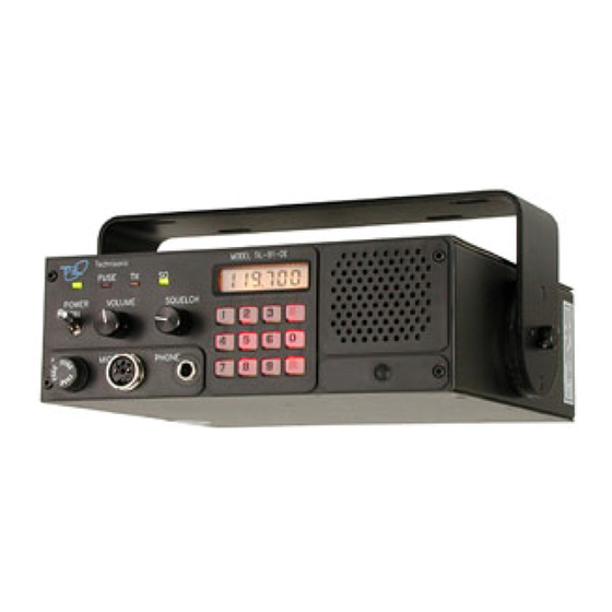
Page 8: Transceiver - General View
Figure 1-1 91-DE Transceiver - General View... - Page 9 Figure 1-2 91-DE Transceiver with Mounting Bracket...
-
Page 10: Power Input Cable Assembly - General View
Figure 1-3 Power Input Cable Assembly - General View... -
Page 11: Microphone Assembly - General View
Figure 1-4 Microphone Assembly - General View... -
Page 12: Antenna Assembly - General View
Figure 1-5 Antenna assembly - General View... -
Page 13: Technical Summary
TECHNICAL SUMMARY A summary of the relevant electrical, operational, mechanical and physical characteristics of the transceiver are given in Table 1-1, Leading Particulars. TABLE 1-1 LEADING PARTICULARS TRANSCEIVER MODEL 91-DE: Power Source Requirements: DC Voltage (Negative Ground)............... 13.75Vdc Nominal Input Current: Transmit Mode.................... - Page 14 TABLE 1-1 LEADING PARTICULARS (CONTINUED) RECEIVER CHARACTERISTICS (Continued) Intermodulation: Levels of Interference Signals Are Shown To Produce Resulting SINAD of Not Less Than 6dB: Ultimate Sensitivity (12dB) SINAD)................... 67dB 30microvolts, Input Signal....................45dB 300microvolts, Input Signal....................30dB Unwanted Radiation............Less Than 80microvolts into 50-ohms Hum and Noise With 1mV RF Signal, 30% modulation at 1kHz: Ratio of Rx Audio Output to Residual Output with 0% modulation......At least 40dB Interference Suppression................
-
Page 15: Installation Information
SECTION 2 INSTALLATION INFORMATION INTRODUCTION This section gives the basic installation information for units of VHF/AM Mobile Transceiver System 910200 in a typical airport service vehicle. As there are many types of vehicles in use, some may require "tailor made" installation information. TRANSCEIVER LOCATION The first consideration when planning an installation in a vehicle is the location of the transceiver. -
Page 16: Antenna Assembly
ANTENNA ASSEMBLY Antenna Assembly, Part Number 861910-1, is supplied as a kit which includes an installation leaflet. The antenna is shown assembled in Figure 1-5. 2.5.1 ANTENNA LOCATION The antenna location is a very important factor in determining the performance of the system. The antenna may be mounted on any flat surface, roof, cowl, fender or rear deck of the vehicle, however, rooftop mounting is recommended for best performance. -
Page 17: Microphone Installation
MICROPHONE INSTALLATION Refer to Figure 1-4 for a general view of the microphone and retaining bracket. Determine a suitable and convenient location for Retaining Bracket and secure it using appropriate hardware (not provided). Connect the connector of Microphone, Part Number 961070-1 to the MIC/PTT connector located on the front panel of the transceiver. -
Page 18: Operational Check
2.10 OPERATIONAL CHECK Perform an operational check of the transceiver, checking each channel in use in both the transmit and receive modes of operation, using the Operating instructions given in Section 3 of this document and the appropriate specified operating procedures during transmission. -
Page 19: Operating Instructions
OPERATING INSTRUCTIONS INTRODUCTION 3.1.1 Transceiver Model TiL-91-DE P/N 901006-2 The Transceiver is a microprocessor controlled VHF/AM transceiver operating over the entire band of 117.975 to 138.000 MHz in 25 KHz steps. The transceiver will store ten user selected frequency channels in addition to the resident emergency channel of 121.500 MHz. Frequency Selection, Storage, Recall, Channel Scan, Search, and Toggle modes are all selected by the 12 key keypad. - Page 20 Figure 3-1 91-DE Mobile Transceiver Front and Rear Panel Layout...
- Page 21 TABLE 3-1 OPERATORS SWITCHES, CONTROLS AND INDICATORS SWITCHES CONTROLS & FUNCTIONAL DESCRIPTION INDICATORS POWER A toggle switch applies the 13.7 volts nominal power supply to the ON/OFF transceiver. The transceiver is switched to ON in the toggle UP position and SWITCH is switched OFF in the toggle DOWN position.
- Page 22 TABLE 3-1 OPERATORS SWITCHES, CONTROLS AND INDICATORS (Continued) SWITCHES CONTROLS & FUNCTIONAL DESCRIPTION INDICATORS LIQUID A 5½ digit Liquid Crystal Display (LCD) displays the FREQUENCY/ CRYSTAL CHANNEL that the transceiver is currently operating on. In SCAN mode it DISPLAY displays the current frequency scanned if RF signal is present. LOUDSPEAKER An 8-ohm internal speaker reproduces the receiver audio output.
-
Page 23: Front Panel Keypad Operation
FRONT PANEL KEYPAD OPERATION All frequencies within the range of 117.975 MHz to 138.000 MHz (25 KHz spacing) can be stored on channels 0 to 9. Channels and feature settings are stored in non-volatile memory. Removal of external power source or batteries will not erase stored channels, key "Beep" set up, Keypad and LCD display lighting set up, 90 second Tx time-out set up or Tx Inhibit selections. - Page 24 3.3.1 Keypad "Beeps" Audible "Beeps" are generated when a key is pressed (default condition). Tones can be enabled/disabled by toggling the "E","8" keys. Press to disable Key "Beeps". Press to enable Key "Beeps". 3.3.2 Keypad and LCD Display Lighting Three Display and keypad lighting modes are available to the operator. The default mode provides no keypad or LCD display backlighting.
- Page 25 NOTE Entry of 117 MHz fills 975 in remaining digits. Entry of 138 Mhz fills 000 in remaining digits. 4th Digit - Can be any digit. 5th + 6th Digits are paired. Entry of 5th digit 0 results in 00 displayed. Entry of 2 results in 25.
- Page 26 Press Frequency 119.750 MHz is stored as channel 1. Press 138.000 MHz as channel 2. 3.3.6 Recalling a Stored Channel To recall the permanently stored emergency channel 121.500 MHz press "E","0". Press "R","#". The frequency stored as the channel indicated will be displayed on the screen. Example: Press Channel 1 frequency 119.750 MHz stored in the previous example will be displayed.
- Page 27 3.3.8 Toggling Between Two Channels Press to recall previous channel. Example: Recall Channel 0 as described in para 4.3.6 117.975 will be displayed. Recall Channel 2 138.000 will be displayed. Press 117.975 will be displayed. Press 138.000 will be displayed. 3.3.9 Search Mode In SEARCH MODE the receiver steps through each stored channel until a transmitted signal is found.
- Page 28 NOTE PTT is inhibited during SCAN mode. Pressing PTT once exits SCAN mode. Pressing PTT twice is required to Key the Transmitter. Press to enter SCAN mode. Press PTT to Lock on SCANned Frequency or Press to exit SCAN. 3-10...
- Page 29 Figure 3-2 Fixed Channel Jumper Locations 3-11...
-
Page 30: Fixed Channel Frequency Set Up
FIXED CHANNEL FREQUENCY SET UP The following procedure fixes preselected channel frequencies and inhibits transmit on receive only channels. After completion of this procedure the operator will be able select stored channels only for receive or transmit. Keypad entry of frequencies is disabled. 3.4.1 System Configuration Configure channel frequencies as desired (Refer to Section 3.3.5). - Page 31 Recall Channel "0" frequency. Channel "0" frequency displayed shall be the same frequency entered before Locking the operating configuration (ie. different from the frequency entered in step 4). Perform Steps 4 through 6 for each channel. 3-13...
Need help?
Do you have a question about the TiL-91-DE and is the answer not in the manual?
Questions and answers