Table of Contents
Advertisement
Quick Links
TMS-110
VHF AM TRANSCEIVER
Installation and Operating
Instructions
TiL Document No. 15RE532
Rev. J
March 2024
Firmware Front Panel Version 1.4.0
Firmware RF Module Version 1.5.0
Technisonic Industries Limited
240 Traders Boulevard, Mississauga, Ontario L4Z 1W7
Tel: (905) 890-2113 Fax: (905) 890-5338
www.til.ca
Copyright by Technisonic Industries Limited. All rights reserved.
Advertisement
Table of Contents

Subscribe to Our Youtube Channel
Related Manuals for TIL TMS-110


Summary of Contents for TIL TMS-110
- Page 1 TMS-110 VHF AM TRANSCEIVER Installation and Operating Instructions TiL Document No. 15RE532 Rev. J March 2024 Firmware Front Panel Version 1.4.0 Firmware RF Module Version 1.5.0 Technisonic Industries Limited 240 Traders Boulevard, Mississauga, Ontario L4Z 1W7 Tel: (905) 890-2113 Fax: (905) 890-5338 www.til.ca...
- Page 2 TECHNISONIC INDUSTRIES LIMITED This page is intentionally left blank. TMS-110 Installation & Operating Instructions TiL 15RE532 Rev. J...
- Page 3 TECHNISONIC INDUSTRIES LIMITED REVISION HISTORY [ 15RE532 ] For the most current revision of this document, please check the Technisonic website: www.til.ca EDITED PAGE DESCRIPTION DATE Original Document Release. Jan. 8, 2016 Updated to final installation and operation for May 24, 2018 production release.
- Page 4 TECHNISONIC INDUSTRIES LIMITED This page is intentionally left blank. TMS-110 Installation & Operating Instructions TiL 15RE532 Rev. J...
- Page 5 WARRANTY INFORMATION The Model TMS-110 is under warranty for one year from the date of purchase. Failed units caused by defective parts or workmanship should be returned to: Technisonic Industries Limited...
- Page 6 TECHNISONIC INDUSTRIES LIMITED This page is intentionally left blank. TMS-110 Installation & Operating Instructions TiL 15RE532 Rev. J...
-
Page 7: Table Of Contents
Recalling a Channel with the Volume Knob ..............19 3.4.5 Recalling a Channel with the Channel Up / Down Keys ..........19 3.4.6 Recalling a Channel with the Recall Feature .............. 19 3.4.7 Deleting a Channel* ....................19 TMS-110 Installation & Operating Instructions TiL 15RE532 Rev. J... - Page 8 Mic RJ45 Connections ....................17 Function Menu Commands .................... 20 Configuration Menu Commands ..................25 25 kHz Channel Spacing ....................29 ICAO 25 kHz and 8.33 kHz Channel Spacing ..............29 Error Codes........................30 TMS-110 Installation & Operating Instructions TiL 15RE532 Rev. J viii...
- Page 9 TECHNISONIC INDUSTRIES LIMITED This page is intentionally left blank. TMS-110 Installation & Operating Instructions TiL 15RE532 Rev. J...
-
Page 10: Introduction
This publication provides information on the installation and operation of the TMS-110 Transceiver System. DESCRIPTION The TMS-110 (TiL system number 180001) includes the TDAM-1000 VHF AM mobile transceiver [Product Marketing Name (PMN) TDAM-1000], operates in the aeronautical VHF AM band, and is designed for ground vehicle installation. - Page 11 TECHNISONIC INDUSTRIES LIMITED This page is intentionally left blank. TMS-110 Installation & Operating Instructions TiL 15RE532 Rev. J...
-
Page 12: General
TECHNISONIC INDUSTRIES LIMITED SECTION 2: INSTALLATION INSTRUCTIONS GENERAL This section contains information and instructions for the correct installation of the TMS-110 VHF AM mobile transceiver system. EQUIPMENT PACKING LOG Unpack the equipment and check for any damage that may have occurred during transit. Save the original shipping container for returns due to damage or warranty claims. -
Page 13: Outline Drawing For Model Tdam-1000 (Top/Front/Side)
TECHNISONIC INDUSTRIES LIMITED FIGURE 1: Outline Drawing for Model TDAM-1000 (Top / Front / Side) TMS-110 Installation & Operating Instructions TiL 15RE532 Rev. J... -
Page 14: Outline Drawing For Model Tdam-1000 (Bottom/Rear/Side)
TECHNISONIC INDUSTRIES LIMITED FIGURE 2: Outline Drawing for Model TDAM-1000 (Bottom / Rear / Side) TMS-110 Installation & Operating Instructions TiL 15RE532 Rev. J... -
Page 15: Installation - Connections
Ground Remote PTT CAN L SPI CS0 SPI MOSI I2C SDA I/O 1 Squelch Out Headset Audio Monitor Audio TABLE 2: Accessory Connections – J3 (26-Pin HDD) – Use MALE Connector TMS-110 Installation & Operating Instructions TiL 15RE532 Rev. J... -
Page 16: Installation - Wiring Instructions
2.5.7. J3 PIN 6 – REMOTE MIC AUDIO This is a microphone audio input. Mic DC bias voltage is supplied. This can be used when a remote user position is required, leave unconnected otherwise. TMS-110 Installation & Operating Instructions TiL 15RE532 Rev. J... -
Page 17: 2.5.8. J3 Pin 18 - Remote Ptt Input
The antenna should be at least 52” from any other antenna. The TMS-110 is supplied with antenna 181299-1 (before March 2024) or 181299-2 (after March 2024). The 181299-1 antenna can be assembled using the following procedure: ... - Page 18 Spread the coax shielding over the antenna base. Trim the shielding to allow the lock nut to be installed. Install and tighten the antenna base lock nut. Install and tighten the antenna base grounding cap. TMS-110 Installation & Operating Instructions TiL 15RE532 Rev. J...
- Page 19 Place the rubber seal around the antenna base. Screw on the antenna base insulator and tighten. Bend the center conductor over into one of the grooves cutting off excess length. Screw on the antenna whip. TMS-110 Installation & Operating Instructions TiL 15RE532 Rev. J...
-
Page 20: Installation - Antenna 181299-2
2.6.1 INSTALLATION – ANTENNA 181299-2 Antenna 181299-2 is supplied with each TMS-110 after March 2024. It uses a standard NMO type mount. The whip has been pre-tuned at Technisonic to cover 118 – 138 MHz. To install the 181299-2 antenna, follow these steps: ... -
Page 21: Installation - Mounting Bracket
The radio may be mounted above or the below the bracket depending on the installation. Use the four 8-32 x 5/16” black screws to attach the radio to the bracket. The bracket has slots to allow the angle to be adjusted. TMS-110 Installation & Operating Instructions TiL 15RE532 Rev. J... -
Page 22: Installation - Microphone
Plug the supplied power cord into power jack (J1) on the back of the radio and tighten both of the mating screws. Route the red wire to the accessories supply of the vehicle, cutting off any excess. Connect the black wire to the vehicle chassis ground. TMS-110 Installation & Operating Instructions TiL 15RE532 Rev. J... - Page 23 TECHNISONIC INDUSTRIES LIMITED This page is intentionally left blank. TMS-110 Installation & Operating Instructions TiL 15RE532 Rev. J...
-
Page 24: General
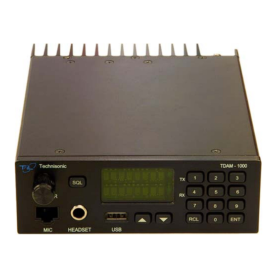
Split frequency pairs Transmit DTMF keypad Scanning of selected channels High and Low power 3.3. FRONT PANEL Refer to figure 3 below: FIGURE 4: TDAM-1000 Front Panel Controls TMS-110 Installation & Operating Instructions TiL 15RE532 Rev. J... -
Page 25: Volume Knob
The supplied hand mic is plugged into the RJ-45 type jack. Headphones if desired can be plugged into the headset jack. The internal speaker and external speaker output can be disabled (default) when the headset jack is used depending on the settings in the configuration menu. TMS-110 Installation & Operating Instructions TiL 15RE532 Rev. J... -
Page 26: Mic Rj45 Connections
TECHNISONIC INDUSTRIES LIMITED PIN # DESCRIPTION Channel Up (Not Used) Chassis Ground Push to Talk MIC Ground MIC Audio Not Connected Channel Down (Not Used) TABLE 3: Microphone (RJ45) Connections TMS-110 Installation & Operating Instructions TiL 15RE532 Rev. J... -
Page 27: Normal Operation
The channel is programmed and the radio is ready to use on the above frequency. If the second enter is not pressed or the mic is keyed within 3 seconds, the new frequency will not be saved in a channel. TMS-110 Installation & Operating Instructions TiL 15RE532 Rev. J... -
Page 28: Recalling A Channel
Recall the desired channel using one of the above methods. Press 0 and enter. The lower line of the display will read ‘DELETE?’ Press enter again to confirm. For example, to delete channel 48, press: The radio will then tune to the next lower channel number available. TMS-110 Installation & Operating Instructions TiL 15RE532 Rev. J... -
Page 29: Function Menu
Read channel or configuration data from the USB storage device into the radio. See Section 3.5.1. Save the channel or the configuration data to the USB storage device from the radio. See Section 3.5.1. TABLE 4: Function Menu Commands TMS-110 Installation & Operating Instructions TiL 15RE532 Rev. J... -
Page 30: Programming With Usb Storage Device
Receive – RX Frequency (6 digits, 128075 is 128.075MHz) Transmit – TX Frequency (6 digits, 128075 is 128.075MHz) Scan – Channel in scan list (Yes or No) Rx Only – RX only channel, TX disabled (Yes or No) TMS-110 Installation & Operating Instructions TiL 15RE532 Rev. J... -
Page 31: Editing The Radio Configuration File
- The radio configuration has now been copied onto the USB stick. - Remove the USB stick from the TDAM-1000. - Plug the USB stick into a PC that has a spreadsheet editor installed. TMS-110 Installation & Operating Instructions TiL 15RE532 Rev. J... - Page 32 - Remove the USB stick from the PC and plug it into the TDAM-1000. - Press - The display will show ‘memory?’ - Press again to toggle the display to show ‘config?’ - Press to confirm. TMS-110 Installation & Operating Instructions TiL 15RE532 Rev. J...
-
Page 33: Updating The Radio Firmware
*Note – Both Front Panel and Main Firmware can be updated at the same time, just put both files on the USB stick. Only one version of each can be on the USB stick at a time. USB must be formatted FAT32 TMS-110 Installation & Operating Instructions TiL 15RE532 Rev. J... -
Page 34: Configuration Menu
Radio is always on when power is applied. Comp Lvl Microphone compression level. Turning the knob will adjust (range 0 – 1023) the maximum gain of the microphone input. Default is 800. TMS-110 Installation & Operating Instructions TiL 15RE532 Rev. J... - Page 35 Level 7- 10W (calibrated to 9.6W across the band at the factory) *Unit will automatically turn TX power level down if input power supply cannot supply enough current or if PA is above rated temperature. TABLE 5: Configuration Menu Commands TMS-110 Installation & Operating Instructions TiL 15RE532 Rev. J...
-
Page 36: Menu Permissions
All the menu permissions as well as the password can also be configured with the Config CSV file. The file can be read from any unit or written to any unit. Editing can be done on a spreadsheet editor. TMS-110 Installation & Operating Instructions TiL 15RE532 Rev. J... - Page 37 5. Once changes are complete turn off radio. Remove ground from TP33 if it is still grounded. 6. Plugin in Speaker cable, and put bottom lid back on the radio. 7. Install all 10 screws. 8. Radio is now ready for use. TMS-110 Installation & Operating Instructions TiL 15RE532 Rev. J...
-
Page 38: 25 Khz Channel Spacing Mode
TABLE 6: 25 kHz Channel Spacing 25 kHz AND 8.33 kHz CHANNEL SPACING MODE The TDAM-1000 is capable of both 25 and 8.33 kHz channel spacing. Contact TiL for instructions to enable 8.33KHz channels. Selecting the desired channel spacing is achieved during the frequency entry procedure (6 digit entry). -
Page 39: Error Codes
Low Input Voltage – 10V or less TX PA Over temperature – PA measuring at 100°C or more Antenna SWR fault PLL Unlocked – Tx or Rx not locked on selected Frequency TABLE 8: Error codes TMS-110 Installation & Operating Instructions TiL 15RE532 Rev. J... - Page 40 TECHNISONIC INDUSTRIES LIMITED This page is intentionally left blank. TMS-110 Installation & Operating Instructions TiL 15RE532 Rev. J...
-
Page 41: Dimensions
Operating Temperature -20 to +55 °C Storage Temperature -40 to +70 °C Power Consumption Transmit High Power (10W) < 80 watts Receive (Max Volume) < 15 watts Standby < 10 watts TMS-110 Installation & Operating Instructions TiL 15RE532 Rev. J... -
Page 42: Receiver Specifications
< 5% @ 90% Modulation Frequency Stability ±1 ppm (0.0001%) Intermodulation Attenuation 40 dB @ 150 kHz Offset Keying Time < 20 ms Release Time < 10 ms Speech Processor 35 dB Dynamic Range TMS-110 Installation & Operating Instructions TiL 15RE532 Rev. J... -
Page 43: Warranty
Technisonic. This Warranty shall not be transferable or assignable to any other persons, firms, or corporations. For warranty registration, please complete the online Warranty Registration Form found at www.til.ca. TMS-110 Installation & Operating Instructions TiL 15RE532 Rev. J...
Need help?
Do you have a question about the TMS-110 and is the answer not in the manual?
Questions and answers