Table of Contents
Advertisement
Quick Links
TDFM-7000
MULTIBAND P25 AIRBORNE TRANSCEIVER
(With Modification No. 3 Installed)
Installation and
Operating Instructions
TiL Document No. 05RE375
Rev. n/c Issue 13
AUGUST 2010
Technisonic Industries Limited
240 Traders Boulevard, Mississauga, Ontario L4Z 1W7
Tel: (905) 890-2113 Fax: (905) 890-5338
www.til.ca
Copyright by Technisonic Industries Limited. All rights reserved.
Advertisement
Table of Contents

Subscribe to Our Youtube Channel
Related Manuals for TIL TDFM-7000


Summary of Contents for TIL TDFM-7000
- Page 1 TDFM-7000 MULTIBAND P25 AIRBORNE TRANSCEIVER (With Modification No. 3 Installed) Installation and Operating Instructions TiL Document No. 05RE375 Rev. n/c Issue 13 AUGUST 2010 Technisonic Industries Limited 240 Traders Boulevard, Mississauga, Ontario L4Z 1W7 Tel: (905) 890-2113 Fax: (905) 890-5338 www.til.ca...
- Page 2 USA that are capable of wide band (25kHz) channel spacing in the commercial 2 way mobile / base sections of the VHF and UHF bands. TDFM-7000 transceivers delivered to the USA after this date will no longer support wide band...
- Page 3 5 2-10 Tables 2.1 & 2.2 updated/changed Revisions made to the tone/code tables (PL and DPL) that are supported by the TDFM-7000 3-6,7 Fig 3.2 split in half and enlarged. JUN 2009 Appendix is now section 3.18. 3.19 added for...
- Page 4 REVISION HISTORY [ 05RE375 ] SECTION EDITED DESCRIPTION DATE - PAGE - Added Information about Auto Test feature with Iss 12 2-15 JUL 2012 Aeroflex 3920 Digital Test Set Jan 01, 2013 FCC narrowband notice added JAN 2013 Iss 13...
- Page 5 Changes or modifications not expressly approved by Technisonic Industries could void the user’s authority to operate the equipment. This manual is designed to provide information about the TDFM-7000. Every effort has been made to make this manual as complete and accurate as possible.
- Page 6 FAA or Transport Canada. Only authorized factory dealers/installers are permitted to download and make use of these documents on behalf of their customers (end users) in support of regulatory agency approval. Please refer to the Technisonic web site www.til.ca for the latest issue of available STCs and letter of authorization for use.
-
Page 7: Table Of Contents
CHANNEL UP AND CHANNEL DOWN – J1 PINS 16 AND 17 ........3.15 LH DATA, SB9600 BUSY, OPTB+, CTS OUT, BOOT DIN, RTSBIN AND RS232DIN – J1 PINS 18 THROUGH 24 ................... 3.16 PANEL BACKLIGHTING – J1 PIN 25 ..............TDFM-7000 Installation & Operating Instructions TiL 05RE375 Rev n/c Issue 13... - Page 8 FIGURE TITLE PAGE Front Panel Controls – TDFM-7000 Transceiver ............. PC 7000(II) Programming cable for TYPE II radios P/N 047365-1 ......Encryption Keyload cable for TYPE I and TYPE II radios P/N 037348-1) ....TYPE I Programming cable P/N 037347-1 .............
-
Page 9: General Description
II RF modules as the type I modules have limited availability. However type I modules are fully supported and either some or all of the TDFM-7000’s RF modules can be type I. If a unit is built with both types, two different programming software packages will have to be purchased. - Page 10 TECHNISONIC INDUSTRIES LIMITED www.til.ca TDFM-7000 Model Variations with type I Modules 3 Band TDFM-7000 Model Variations (-7XXX) TDFM-7000, P/N 051240-1-7XXX/P7YYY GREEN display. TDFM-7000, P/N 051240-2-7XXX/P7YYY RED display. TDFM-7000NV, P/N 051240-1-7XXXNV/P7YYY GREEN NV display. 4 Band TDFM-7000 Model Variations (-7XXXX) TDFM-7000, P/N 051240-1-7XXXX/P7YYY GREEN display.
-
Page 11: Technical Characteristics
0.35 0.45 *Digital 5% BER (12.5kHz) 0.25 0.25 0.25 **Analog with 12dB SINAD 0.25 0.25 0.25 Selectivity in dB: 25 kHz Channel 12.5 kHz Channel Intermodulation (dB) * ** TDFM-7000 Installation & Operating Instructions TiL 05RE375 Rev n/c Issue 13... - Page 12 Intermodulation * ** *Measured in digital mode per TIA / EIA IS 102.CAAA under nominal conditions. ** Measured in analog mode per TIA / EIA 603 under nominal conditions. TDFM-7000 Installation & Operating Instructions TiL 05RE375 Rev n/c Issue 13...
-
Page 13: Operating Instructions
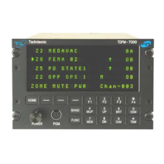
It is possible to connect the transceiver such that both methods are used. FRONT PANEL Refer to the diagrams below: FIGURE 2.1 Front Panel Controls – TDFM-7000 Transceiver TDFM-7000 Installation & Operating Instructions TiL 05RE375 Rev n/c Issue 13... -
Page 14: Power Switch
For example, programming a soft key to CHAN would be redundant since there is already a channel function using the knobs. Using the CHAN soft key would also not update the channel number on the display, causing some confusion. TDFM-7000 Installation & Operating Instructions TiL 05RE375 Rev n/c Issue 13... -
Page 15: Band Key
Pressing the BAND key will select the next band in sequence. A solid arrow will indicate which band is selected. If the TDFM-7000 audio routing (see the configuration menu) is set up in single mode, the band key also acts as the transmit select. - Page 16 It is possible to use Motorola’s Customer Programming Software (CPS™) to alter the default keypad settings of the TDFM-7000 radio. However if custom key settings are chosen it will not be possible for Technisonic to help the Pilot or other Radio User through operational difficulties.
-
Page 17: Mup(4) And Mdn(7) Keys (Memory Up And Down Keys)
LED on the right side of each line indicates transmit. A solid arrow on the first character indicates which band is selected. The fifth line displays the menu items associated with the band selected and the mode the knob is in. TDFM-7000 Installation & Operating Instructions TiL 05RE375 Rev n/c Issue 13... -
Page 18: General Operation
Switch on the transceiver as described in 2.3. Select the desired band by pressing the BAND key. Select the TDFM-7000 on the aircraft audio panel. Press the knob again so that CHAN shows up on the top right of the display. Rotate the knob until the desired channel or talk group is selected. -
Page 19: Pc 7000(Ii) Programming Cable For Type Ii Radios P/N 047365-1
Motorola KVL-3000+ Keyloader. Same P/N for type I or type II modules. FIGURE 2.2 PC 7000(II) Programming cable for TYPE II radios P/N 047365-1 FIGURE 2.3 Encryption Keyload cable for TYPE I and TYPE II radios P/N 037348-1 TDFM-7000 Installation & Operating Instructions TiL 05RE375 Rev n/c Issue 13... - Page 20 Service (see following page). A Motorola Radio Interface Box (RIB) is required to connect the computer to the TDFM-7000 if Type I modules are installed. Each band in the TDFM- 7000 is considered a Type I (XTS-3000) portable by the CPS™ software. To program a band in the transceiver, it must be selected by pressing the BAND key before running the CPS™.
-
Page 21: Type I Programming Cable P/N 037347-1
TECHNISONIC INDUSTRIES LIMITED www.til.ca FIGURE 2.4 TYPE I Programming cable P/N 037347-1 FIGURE 2.5 Motorola RIB box for TYPE I Radios P/N RLN 1015D TDFM-7000 Installation & Operating Instructions TiL 05RE375 Rev n/c Issue 13... - Page 22 Select the com port that is the virtual port created by the adaptor. Click APPLY, then OK. The CPS should now work with the USB to serial adaptor. TDFM-7000 Installation & Operating Instructions TiL 05RE375 Rev n/c Issue 13 2-10...
-
Page 23: Configuration Menu
2.17 CONFIGURATION MENU Some features of the TDFM-7000 transceiver can be configured to the user’s preference. To enter the configuration menu, turn the unit on while simultaneously pressing the F4, ESW and TSW keys. Hold the keys until the display reads ‘Configuration Menu’. The following menu items can be changed or modified. -
Page 24: Keyloading Mode
Follow the software instructions. During the flash procedure, the software will ask you to turn off and on the radio, use the RESET soft-key, do not turn off the transceiver. TDFM-7000 Installation & Operating Instructions TiL 05RE375 Rev n/c Issue 13 2-12... -
Page 25: Front Panel Programming (Fpp) Mode - Optional
Press ‘OK’ when done. There will be NAME a delay while the channel is saved, then the display will return to normal. TDFM-7000 Installation & Operating Instructions TiL 05RE375 Rev n/c Issue 13 2-13... - Page 26 TECHNISONIC INDUSTRIES LIMITED www.til.ca MOTOROLA TONE /CODE TABLE FOR THE TDFM-7000 SERIES The following is a list of TDFM-7000 SERIES PL(Hz)/MOT CODES: PL(Hz) MCODE PL(Hz) MCODE PL(Hz) MCODE PL(Hz) MCODE 67.0 97.4 141.3 206.5 69.3 100.0 146.2 210.7 71.9 103.5 151.4...
-
Page 27: Autotest Cabability
2.21 AUTOTEST CABABILITY The TDFM-7000 series of radios are equipped with an Autotest feature that will greatly reduce the time it takes to align and test the radios performance. Technisonic has teamed up with Aeroflex to provide the user with advance tools to manage there fleet of radios. - Page 28 TECHNISONIC INDUSTRIES LIMITED www.til.ca This page left intentionally blank. TDFM-7000 Installation & Operating Instructions TiL 05RE375 Rev n/c Issue 13 2-16...
-
Page 29: Installation Instructions
INSTALLATION The TDFM-7000 Transceiver is designed to be Dzus mounted and should be installed in conjunction with an IN-7000 installation kit. See Figure 3.1 for an outline drawing of the unit with dimensions to facilitate the installation. -
Page 30: Outline Drawing
TECHNISONIC INDUSTRIES LIMITED www.til.ca FIGURE 3.1 Outline Drawing for Model TDFM-7000 TDFM-7000 Installation & Operating Instructions TiL 05RE375 Rev n/c Issue 13... -
Page 31: Installation - Pin Locations And Connections
J2 (9 Pin D Connections) – Use FEMALE Connector Pin # Description Ground Audio Combined PTT 4 PTT Combined Audio 4 Mic 4 Mic Combined On Power Speaker Combined TABLE 3.2 Wire connections TDFM-7000 Installation & Operating Instructions TiL 05RE375 Rev n/c Issue 13... -
Page 32: Installation - Wiring Instructions
Programming Software (CPS™) or encryption key loading and are left unconnected. They may be used to update the radio once it is removed from the aircraft. These pins are also brought out to the TDFM-7000’s front panel mini-DIN connector to allow programming in the aircraft. -
Page 33: Panel Backlighting - J1 Pin
If you attempt to turn off the radio with the jumper installed, it will just come back on again in 5 seconds. Turning the avionics bus or battery master switch off will now be required to de-energize the radio. TDFM-7000 Installation & Operating Instructions TiL 05RE375 Rev n/c Issue 13... - Page 34 TECHNISONIC INDUSTRIES LIMITED www.til.ca FIGURE 3.2a Wiring connections for the TDFM-7000 Transceiver TDFM-7000 Installation & Operating Instructions TiL 05RE375 Rev n/c Issue 13...
- Page 35 OPTIONAL RECEIVE ATTENUATOR. CAN BE USED ON ANY BAND AS REQUIRED FOR TRUNKING SYSTEMS. SWITCH SHOULD BE MOUNTED ON THE PANEL NEAR THE TDFM-7000. THE ON POSITION SHOULD BE LABELED 'IN FLIGHT' AND THE OFF POSTION LABELED WITH 'ON GROUND' FIGURE 3.2b Wiring connections for the TDFM-7000 Transceiver...
-
Page 36: Post Installation Emi Test
3.18 POST INSTALLATION EMI TEST PURPOSE The purpose of this test is to identify any interference that the TDFM-7000 transceiver may cause with existing aircraft systems. TEST CONDITIONS The TDFM-7000 transceiver should be installed and function tested. The antenna VSWR should be checked. - Page 37 For example it is permissible for a VFR certified GPS to lose navigation capability while the TDFM-7000 unit is transmitting, providing that it recovers properly and promptly, but it is not permissible for an IFR Approach certified GPS to be affected in the same way.
- Page 38 Determine if the image frequency for the VHF Comm falls within the range of the TDFM- 7000. If so, select a set of frequencies that will cause the TDFM-7000 to be set as close as possible to the image frequency. Any one of the many possible sets will suffice. Record those values in the spaces provided in the following chart.
- Page 39 Determine if the image frequency for the VOR/ILS Nav falls within the range of the TDFM- 7000. If so, select two sets of frequencies that will cause the TDFM-7000 to be set as close as possible to the image frequency. Choose one set in the localizer frequency range and one in the VOR frequency range.
- Page 40 With a portable glide slope generator, provide enough signal to firmly activate the indicator needle and hide all flags. Increase the signal level by 3 dB. Modulate the TDFM-7000 transmitter on the following frequencies for at least 20 seconds. Observe the Glide Slope displays.
- Page 41 TDFM-7000 PASS FAIL 334.7 (108.1) 167.35 NOTES: Operate the TDFM-7000 transmitter on the following frequency for at least 20 seconds. Observe the Transponder for any spurious replies or loss of reply to test set. FREQUENCIES TRANSPONDER #1 TRANSPONDER #2 TDFM-7000...
- Page 42 TECHNISONIC INDUSTRIES LIMITED www.til.ca Modulate the TDFM-7000 transmitter on the following frequencies for at least 20 seconds. Observe the DME displays. Look for loss of distance information on the display. FREQUENCIES RESULTS DME 1 TDFM-7000 PASS FAIL 978 (108.0) 1020 (112.1)
- Page 43 Frequency #2 Frequency #3 At a safe altitude engage the autopilot or stability augmentation system. Modulate the TDFM-7000 transmitter on the above frequencies for at least 20 seconds. Observe any effect on the autopilot or stability augmentation system. Observations: Perform a coupled ILS approach to the aircraft's certified limits. Modulate the TDFM-7000 transmitter on the above frequencies for at least 20 seconds.
- Page 44 Glideslope 1&2 (UHF Lo, UHF Hi, and 800 MHz) VOR/LOC 1&2 (UHF Lo, UHF Hi, and 800 MHz) Compass Directional Gyro Fuel Pressure Oil Temp Amps Bus Voltage TDFM-7000 Installation & Operating Instructions TiL 05RE375 Rev n/c Issue 13 3-16...
- Page 45 TECHNISONIC INDUSTRIES LIMITED www.til.ca Fuel % Torque % Annunciators Digital Clock Oil Pressure DME 1&2 (VHF, UHF Lo, and 800 MHz) GPS 1&2 (UHF Lo and 800 MHz) TDFM-7000 Installation & Operating Instructions TiL 05RE375 Rev n/c Issue 13 3-17...
- Page 46 TECHNISONIC INDUSTRIES LIMITED www.til.ca STEP SYSTEM PASS FAIL NOTES NOTES: TDFM-7000 Installation & Operating Instructions TiL 05RE375 Rev n/c Issue 13 3-18...
-
Page 47: Tdfm-7000/7300 Software Option For Control Of Latitude Satellite Gateway S200-Sg11
The TDFM-7000/7300 software option for control of the Latitude satellite gateway S200- SG11 allows the TDFM-7000 to act as a controller for the above system replacing the usual controller thereby saving space and weight in the aircraft and providing a larger display and keypad. -
Page 48: 3.19.3 Operating Instructions
Pressing the [*] key will invoke the download function. The pre- programmed messages, email addresses and phone numbers can be downloaded into the radio using Technisonic’s MultiTDP software. TDFM-7000 Installation & Operating Instructions TiL 05RE375 Rev n/c Issue 13 3-20... -
Page 49: Satcom Menus
2 = T e x t M S G 3 = G P S I n f o H O M E = E x i t * = P R G TDFM-7000 Installation & Operating Instructions TiL 05RE375 Rev n/c Issue 13 3-21... - Page 50 # 0 : 0 0 1 9 0 5 8 9 0 2 1 1 3 H O M E = E x i t * = O N / O F F TDFM-7000 Installation & Operating Instructions TiL 05RE375 Rev n/c Issue 13 3-22...
- Page 51 # = D E L button toggles H O M E = E x i t * = U P D between MSG and ADDR. TDFM-7000 Installation & Operating Instructions TiL 05RE375 Rev n/c Issue 13 3-23...
- Page 52 Press [ FUNC + 6 ] [ Satcom menu / incoming call ], Press [ * ]answer the incoming call, Press [ # ] reject the incoming call, Press [ HOME ] for previous menu. TDFM-7000 Installation & Operating Instructions TiL 05RE375 Rev n/c Issue 13 3-24...
-
Page 53: Appendix A Support Notes
(login required). For the latest Software Release(s) refer to the Publication Index list under the section for • this model’s software/firmware history index (login required). TDFM-7000 Installation & Operating Instructions TiL 05RE375 Rev n/c Issue 13... - Page 54 TECHNISONIC INDUSTRIES LIMITED www.til.ca APPENDIX A - Support Notes NOTES TDFM-7000 Installation & Operating Instructions TiL 05RE375 Rev n/c Issue 13...
-
Page 55: Warranty
Technisonic. This Warranty shall not be transferable or assignable to any other persons, firms or corporations. For warranty registration please complete the on-line Warranty Registration Form found at www.til.ca.
Need help?
Do you have a question about the TDFM-7000 and is the answer not in the manual?
Questions and answers