Table of Contents
Advertisement
Quick Links
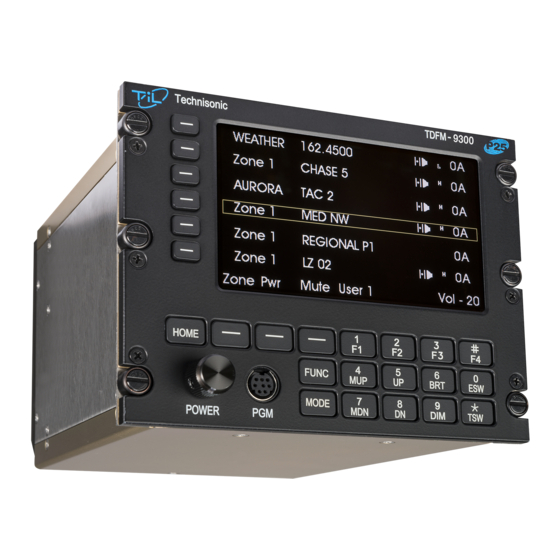
TDFM-9300
MULTIBAND P25 AIRBORNE TRANSCEIVER
Installation Instructions
TiL Document No. 13RE471
Rev. D
Issue 5
NOVEMBER 2015
Technisonic Industries Limited
240 Traders Boulevard, Mississauga, Ontario L4Z 1W7
Tel: (905) 890-2113 Fax: (905) 890-5338
www.til.ca
Copyright by Technisonic Industries Limited. All rights reserved.
Advertisement
Table of Contents

Subscribe to Our Youtube Channel
Related Manuals for TIL TDFM-9300


Summary of Contents for TIL TDFM-9300
- Page 1 TDFM-9300 MULTIBAND P25 AIRBORNE TRANSCEIVER Installation Instructions TiL Document No. 13RE471 Rev. D Issue 5 NOVEMBER 2015 Technisonic Industries Limited 240 Traders Boulevard, Mississauga, Ontario L4Z 1W7 Tel: (905) 890-2113 Fax: (905) 890-5338 www.til.ca Copyright by Technisonic Industries Limited. All rights reserved.
- Page 3 TECHNISONIC INDUSTRIES LIMITED REVISION HISTORY [ 13RE471 ] For the most current revision of this document, please check the Technisonic website: www.til.ca EDITED PAGE DESCRIPTION DATE Corrected DO-160 Information. Jul. 2013 Front Page Front Panel Image changed. Oct. 2013 A – 1 1 to 5 Fixed Radio P/N Nomenclature.
- Page 4 TECHNISONIC INDUSTRIES LIMITED This page is intentionally left blank. TDFM-9300 Installation Instructions TiL 13RE471 Rev. D Issue 5...
- Page 5 Changes or modifications not expressly approved by Technisonic Industries could void the user’s authority to operate the equipment. This manual is designed to provide information about the TDFM-9300. Every effort has been made to make this manual as complete and accurate as possible.
- Page 6 TECHNISONIC INDUSTRIES LIMITED SUMMARY OF DO-160G ENVIRONMENTAL TESTING Summary of DO-160G Environmental Testing for Technisonic Model TDFM-9300 Transceiver: CONDITIONS CATEGORY Temperature and Altitude A2, B1, C4, D1 Temperature Variation Humidity Operational Shock and Crash Safety Vibration S, U Magnetic Effect...
-
Page 7: Table Of Contents
ANTENNA SELECTION AND INSTALLATION CONSIDERATIONS ......21 2.23 POST INSTALLATION ADJUSTMENT ................22 2.24 POST INSTALLATION EMI TEST ................. 24 APPENDIX A Support Notes ..................35 ENVIRONMENTAL QUALIFICATION FORM ..............36 WARRANTY ........................38 TDFM-9300 Installation Instructions TiL 13RE471 Rev. D Issue 5... - Page 8 TDFM-9300 Band Display Orientation ................9 Wiring Connections for Individual Band Control ............17 Wiring Connections for Combined Band Control ............18 Wiring Connections for MCP Features ................19 Wiring Connection Notes for the TDFM-9300 Transceiver ..........20 LIST OF TABLES TABLE TITLE PAGE J1 25-Pin D Connections ....................
-
Page 9: Introduction
AES and/or DES-OFB encryption with OTAR in any of the available modules. Bands 1 through 4 on the TDFM-9300 are not normally frequency agile. In order to have the ability to change the frequencies at the front panel, the FPP (front panel programming) option must be ordered for each band. -
Page 10: Model Variation
TECHNISONIC INDUSTRIES LIMITED MODEL VARIATION There are several variations of the Model TDFM-9300 Transceiver. Each variation offers different features and performance based on the type of RF modules and options installed. RF Modules are mounted in trays of two with up to 3 trays supported. - Page 11 28 volt backlighting. Equipment can be set to operate on 5 V backlighting by using the software based configuration menu. See Section 2.17 Configuration Menu in the TDFM-9300 Operating Instructions manual available at www.til.ca. Damage will not occur if the incorrect voltage is applied.
-
Page 12: Technical Characteristics
12.5 kHz Channel Intermodulation * ** * Measured in digital mode per TIA / EIA IS 102.CAAA under nominal conditions. ** Measured in analog mode per TIA / EIA 603 under nominal conditions. TDFM-9300 Installation Instructions TiL 13RE471 Rev. D Issue 5... - Page 13 -60 dB below carrier level FM Hum And Noise -40 dB Audio Input 50 mV at 2.5 kHz into 200 ohms input circuit for ± 3.5 kHz deviation, adjust. Audio Distortion Less than 5% TDFM-9300 Installation Instructions TiL 13RE471 Rev. D Issue 5...
- Page 14 -60 dB below carrier level Signal to Noise Ratio -35 dB Audio Input 50 mV at 2.5 kHz into 200 ohm input circuit for 30% modulation (adjustable) Audio Distortion Less than 5% TDFM-9300 Installation Instructions TiL 13RE471 Rev. D Issue 5...
-
Page 15: General
INSTALLATION The TDFM-9300 Transceiver is designed to be Dzus mounted and should be installed in conjunction with an IN-9300 installation kit. See Figure 1 for an outline drawing of the unit with dimensions to facilitate the installation. -
Page 16: Outline Drawing
TECHNISONIC INDUSTRIES LIMITED FIGURE 1: Outline Drawing for Model TDFM-9300 TDFM-9300 Installation Instructions TiL 13RE471 Rev. D Issue 5... -
Page 17: Tdfm-9300 Antenna & Connector Locations
TECHNISONIC INDUSTRIES LIMITED FIGURE 2: TDFM-9300 Antenna & Connector Locations BANDS FIGURE 3: TDFM-9300 Band Display Orientation Band display corresponds to the antenna connector numbering and radio ports. Band 1 (top of the display) is connected the ANT 1 and uses the Band 1 connections on the interface connectors. -
Page 18: Installation - Pin Locations And Connections
RX Data Ground Main Power +28 V Down Channel / Band Mic 5 Audio 5 PTT 5 Mic 6 Audio 6 PTT 6 Panel Backlighting TABLE 1: J1 (25-Pin D) Connections TDFM-9300 Installation Instructions TiL 13RE471 Rev. D Issue 5... - Page 19 Audio Ground 5 Audio Ground 6 Audio Ground 3 Audio Ground 4 Audio 1 Audio Ground 1 Ground Audio Combined Ground 1 Audio Combined 1 TABLE 3: J5 (15-Pin HDD) Connections TDFM-9300 Installation Instructions TiL 13RE471 Rev. D Issue 5...
- Page 20 Band 7 PTT In Band 8 PTT In Band 7 Audio In Band 8 Audio In S200-P12 RX Data Digital Audio Panel Data Out TABLE 4: J9 (26-Pin HDD) Connections (MOD 14 Only) TDFM-9300 Installation Instructions TiL 13RE471 Rev. D Issue 5...
- Page 21 20 MHz 40 MHz No connection No connection No connection No connection Tune Indicator No connection Tune Enable Ground No connection No connection TABLE 5: P1 15-Pin High Density D Connections TDFM-9300 Installation Instructions TiL 13RE471 Rev. D Issue 5...
-
Page 22: Installation - Wiring Instructions
There are receive audio, mic audio, and Push To Talk (PTT) lines for each band as well as two sets of lines combining all bands. The TDFM-9300 can be wired such that band selection can be made on the audio panel. Up to 7 positions need to be available on the audio panel;... -
Page 23: Tx Data And Rx Data - J1 Pins 12 And 13
Connect according to the manufacturer’s instructions. In the case of the FLX-3050B, the tune indicator (which is normally connected to a light) can be connected to Pin 10 so that the tuning indication will show on the TDFM-9300 display. If a passive antenna is used, these lines shall remain unconnected. - Page 24 Bendix King Relm KNG P150, P400, P500, P800 179.0745 Sincgars PRC-117, MBITR 179.0600 TABLE 6: List of External Radio Interface Cables NOTE: All the above cables interface the TDFM-9300 via a panel mounted locking DIN connecter P/N 244.0070. TDFM-9300 Installation Instructions TiL 13RE471 Rev. D Issue 5...
-
Page 25: Wiring Connections For Individual Band Control
TECHNISONIC INDUSTRIES LIMITED FIGURE 4: Wiring Connections for Individual Band Control TDFM-9300 Installation Instructions TiL 13RE471 Rev. D Issue 5... -
Page 26: Wiring Connections For Combined Band Control
TECHNISONIC INDUSTRIES LIMITED FIGURE 5: Wiring Connections for Combined Band Control TDFM-9300 Installation Instructions TiL 13RE471 Rev. D Issue 5... -
Page 27: Wiring Connections For Mcp Features
TECHNISONIC INDUSTRIES LIMITED FIGURE 6: Wiring Connections for MCP Features TDFM-9300 Installation Instructions TiL 13RE471 Rev. D Issue 5... -
Page 28: Wiring Connection Notes For The Tdfm-9300 Transceiver
TECHNISONIC INDUSTRIES LIMITED FIGURE 7: Wiring Connection Notes for the TDFM-9300 Transceiver TDFM-9300 Installation Instructions TiL 13RE471 Rev. D Issue 5... -
Page 29: Antenna Selection And Installation Considerations
If dual or tri band RF modules are installed in the TDFM-9300, it is suggested to use a single connector, multiband antenna for each of the RF modules installed. When single band modules are installed, a single band antenna should be used. -
Page 30: Post Installation Adjustment
In the Configuration Menu, select the Backlight Mode – 28 V or 5 V item). Set the dimming bus in the airframe to maximum value. Rotate the knob to adjust the max brightness of the keypad to the desired level. TDFM-9300 Installation Instructions TiL 13RE471 Rev. D Issue 5... - Page 31 Highlight the Menu, Key the module and rotate the knob to adjust as required. NOTE: The Transmit Power Menus are not available for radios equipped with VHF AM and UHF AM RF modules. Transmit power is fixed. Press ESC to return to normal operation. TDFM-9300 Installation Instructions TiL 13RE471 Rev. D Issue 5...
-
Page 32: Post Installation Emi Test
2.24 POST INSTALLATION EMI TEST PURPOSE The purpose of this test is to identify any interference that the TDFM-9300 transceiver may cause with existing aircraft systems. TEST CONDITIONS The TDFM-9300 transceiver should be installed and function tested. The antenna VSWR should be checked. - Page 33 TECHNISONIC INDUSTRIES LIMITED PROCEDURE Operate the TDFM-9300 transmitter on the following frequency for at least 20 seconds. Observe the GPS for any degradation in satellite status or availability or flags. FREQUENCIES GPS #1 GPS #2 TDFM-9300 PASS FAIL PASS FAIL 143.2125 MHz...
- Page 34 Determine if the image frequency for the VHF Comm falls within the range of the TDFM- 9300. If so, select a set of frequencies that will cause the TDFM-9300 to be set as close as possible to the image frequency. Any one of the many possible sets will suffice.
- Page 35 Determine if the image frequency for the VOR/ILS Nav falls within the range of the TDFM-9300. If so, select two sets of frequencies that will cause the TDFM-9300 to be set as close as possible to the image frequency. Choose one set in the localizer frequency range and one in the VOR frequency range.
- Page 36 ILS to be used. Divide the glide slope frequency by 2 and program into the TDFM-9300. Fly the aircraft to intercept the localizer and glide slope (both needles centered) at 26 nm from the runway. Transmit on the TDFM-9300 for 10 seconds and watch for any deflections or flags.
- Page 37 334.7 (108.1) 167.35 334.7 (108.1) 33.4700 NOTES: Operate the TDFM-9300 transmitter on the following frequency for at least 20 seconds. Observe the Transponder for any spurious replies or loss of reply to test set. FREQUENCIES TRANSPONDER #1 TRANSPONDER #2 TDFM-9300...
- Page 38 TECHNISONIC INDUSTRIES LIMITED Modulate the TDFM-9300 transmitter on the following frequencies for at least 20 seconds. Observe the DME displays. Look for loss of distance information on the display. FREQUENCIES RESULTS DME 1 TDFM-9300 PASS FAIL 978 (108.0) 1020 (112.1)
- Page 39 Frequency #2 Frequency #3 At a safe altitude, engage the autopilot or stability augmentation system. Modulate the TDFM-9300 transmitter on the above frequencies for at least 20 seconds. Observe any effect on the autopilot or stability augmentation system. Observations: Perform a coupled ILS approach to the aircraft's certified limits. Modulate the TDFM- 9300 transmitter on the above frequencies for at least 20 seconds.
- Page 40 Amps Bus Voltage Fuel % Torque % Annunciators Digital Clock Oil Pressure DME 1 & 2 (VHF, UHF Lo, and 800 MHz) GPS 1 & 2 (UHF Lo and 800 MHz) TDFM-9300 Installation Instructions TiL 13RE471 Rev. D Issue 5...
- Page 41 TECHNISONIC INDUSTRIES LIMITED STEP SYSTEM PASS FAIL NOTES NOTES: TDFM-9300 Installation Instructions TiL 13RE471 Rev. D Issue 5...
- Page 42 TECHNISONIC INDUSTRIES LIMITED This page is intentionally left blank. TDFM-9300 Installation Instructions TiL 13RE471 Rev. D Issue 5...
-
Page 43: Appendix A Support Notes
For the latest Technical Information Bulletins, refer to the Publication Index list under the section • for this model (login required). For the latest Software Release(s), refer to the Publication Index list under the section for this • model’s software/firmware history index (login required). NOTES TDFM-9300 Installation Instructions TiL 13RE471 Rev. D Issue 5... -
Page 44: Environmental Qualification Form
Operational Shock and Crash Safety Standard Operational Shocks (NOTE-3) Vibration Sinusoidal Vibration – curve M Random Vibration – curve B Sine-On-Random Vibration – curve G Explosive Atmosphere Not tested Waterproofness 10.0 Not tested TDFM-9300 Installation Instructions TiL 13RE471 Rev. D Issue 5... - Page 45 Testing included subparagraph 16.6.1.3b: Requirement for Equipment with Digital Circuits. NOTE-3 Approval for this category is based on similarity to the TDFM-9000. See test report 13RE469. NOTE-4 Only applies to units with “MOD 6” marked on the modifications label. TDFM-9300 Installation Instructions TiL 13RE471 Rev. D Issue 5...
-
Page 46: Warranty
Technisonic. This Warranty shall not be transferable or assignable to any other persons, firms, or corporations. For warranty registration, please complete the online Warranty Registration Form found at www.til.ca. TDFM-9300 Installation Instructions TiL 13RE471 Rev. D Issue 5...
Need help?
Do you have a question about the TDFM-9300 and is the answer not in the manual?
Questions and answers